This thread has been locked.

If you have a related question, please click the "Ask a related question" button in the top right corner. The newly created question will be automatically linked to this question.

LM3409: Problem with current spikes using the LM3409

Part Number: LM3409

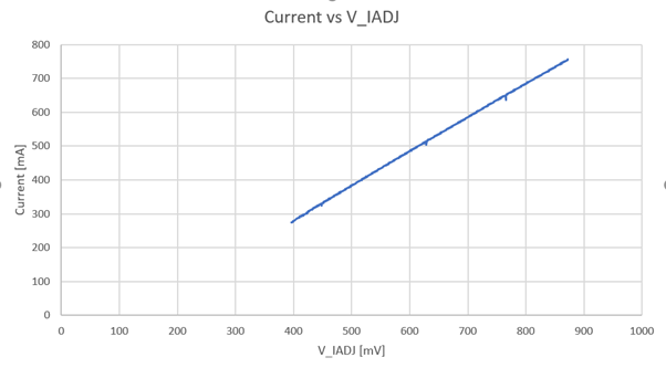
Hi. I'm using an LM3409 MOSFET driver to drive a LED. Apparently, it seems like there are spikes occurring when I make a sweep from lower V_IADJ values to a higher value (see picture 1). These "spikes" occur in different parts of the sweep every time I run a test. It seems like the spikes on this sweep have an offset from the expected true value of about 2.5% but I have seen spikes where the spike offset is about 20%. I have monitored the V_IADJ voltage and nothing seems to be wrong on that end (see picture 2). On Picture 2 I made another test where the A_IADJ has the same voltage for all exposures. Here it's clear that the average output is higher on the first exposure and lower on the second even though the V_IADJ has the same voltage. (The spike at the end is not a problem. It is only the average current that is the problem)

Is this something you can explain or have experienced before?
 Picture 1.

On 

  Picture 2.

  • Hello Oliver,

    The LM3409 regulates peak current using a divided down Viadj as the reference.  Unless the LM3409 is operating incorrect the current should not vary if Viadj doesn't vary.  What do you have connected to VIadj?  Is there an RC filter to eliminate noise at Viadj?  Is your peak to peak current ripple allowing the current sense to see more than 24 mV?  See section 8.3.4 on page 15 of the datasheet.  Can you zoom into the current ripple for both operating points?  Do you have an output capacitor?  If so you may need to look at the inductor current or remove the output capacitor to see the actual inductor current at the output.

    Best Regards,

  • Hi Irwin. The VIADJ you see on the graph is the measured VIADJ and not the theoretical output. The VIADJ does not have an RC filter at the input at this point no. VIADJ is connected to a DAC. The DAC has been tested and everything works as it should. When using equation 8 on page 14 the ripple current should be 381mA but when I zoom in on the measured current the ripple current is only about 45mA. Because of this, my sense resistor ratio to the ripple (equation 11) is no longer as it should be. I have tried increasing the sense resistor but it does not help. In the first picture, you can see the measured current is lower than in the second picture. The current is the red graph and VIADJ is the white graph. The X-axis is time in seconds and the Y-axis is voltage and current. ( current is measured through a shunt).

  • Hi oliver,

    Those pictures look like they are sampling limited.  Either try increasing the number of data samples for the oscilloscope picture or change the time base to get a closer picture of the ripple.  Changing the current sense resistor will change the voltage across it but to increase ripple the switching frequency needs to be reduced or the inductor value decreased.  I'd first get a close look at the above pictures to make sure the oscilloscope picture is correct.

    Best Regards,