This thread has been locked.

If you have a related question, please click the "Ask a related question" button in the top right corner. The newly created question will be automatically linked to this question.

TPS6594-Q1: How to avoid SAFERECOVERY because of UV/OV/Residual

Part Number: TPS6594-Q1

We need to mask UV/OV/residual detection of Vin/Vout which will lock the die .How can we mask the detection ?

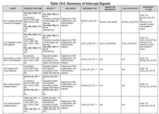
VCC OV/UV: 0X4E  ,is it right?

VCC residual voltage :how to mask ?

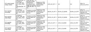
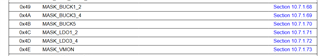
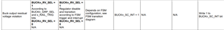
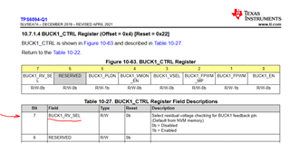
BUCK/LDO vout OV/UV::0x48 /0x49/0x4A/0X4B/0X4C/0X4D ,is it right?

BUCK/LDO vout residual voltage :  how to mask ?


  • Hello,

       The residual voltage check is different in that it cannot be masked.  It can only be enabled and disabled, www.ti.com/.../tps6594-q1.pdf

    There is no residual voltage check on VCCA only the OV and UV monitors.

    The registers you have identified are correct:

    If this is a dual PMIC solution please be sure to mask in both PMICs.  PMICA at address 0x48 and PMICB at adddress 0x4C.

    Regards,

    Chris

  • Hi Chris, What is the difference between mask and disable residual- voltage? How to disable it ?


  • Hello,

    There is no mask for the residual voltage, only disable/enable control.  The control for the residual voltage is found in the BUCKx_CTRL and LDOx_CTRL registers.

    Regards,

    Chris

  • Hi Chris , we have disable BUCK1_RV_SEL ,it may be turned on in BOOTBIST ?We have found this situation  

  • Hello,

    Yes.  THis is correct.  if you make updates during runtime, those values will be returned to the NVM values once the device transitions from INIT to boot bist. 

    So if there is a failure or a power cycle and the device returns to the init state any values written will be returned to the NVM values.

    Regards,

    Chris

  • Hi Chris , Thanks for you rapidly reply!

    I have 2 following questions:

    1 ,  If the UV(input or output) is always present, how long the RECOV_CNT will reach the limit ?What is the time interval for each count increase ?

    2, What detection was done at ABIST and LBIST.?

  • 1 ,  If the UV(input or output) is always present, how long the RECOV_CNT will reach the limit ?What is the time interval for each count increase ?

    If the VCCA UV is always present the PMIC will not attempt to power up until the VCCA UV goes away.

    If the issue is with a regulator, then time is based upon the power-up sequence timing (how long before the rail which has an issue is turned on) and the time of the power down sequence.  Also, the type of error will cause a different response.  In this case, the first error is a BUCK related error resulting in either an MCU or SOC power error.  In the subsequent power on attempts the ABIST fails and this results in a moderate error. The types of errors, sequences, and timings are found in the PDN users guide.

    2, What detection was done at ABIST and LBIST.?

    I am not sure if I can post here, but this is listed on page 17 of the TPS6594x-Q1 Functional Safety Manual.

    Regards,

    Chris