This thread has been locked.

If you have a related question, please click the "Ask a related question" button in the top right corner. The newly created question will be automatically linked to this question.

TPS65217: No battery power supply, USB connected to GND, using AC power supply, would like to know the detailed requirements for AC input

Part Number: TPS65217

HI FAE

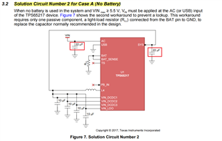
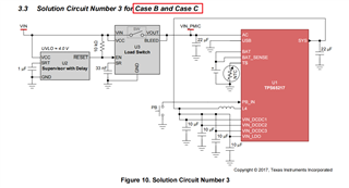
I am using TPS65217 to power AM335x, I would like to know if the PMIC is powered without battery, USB is connected to GND, and powered by AC, I would like to know the detailed requirements for AC input

What is currently understood from the datasheet is that

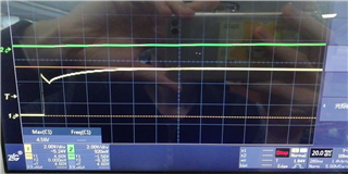
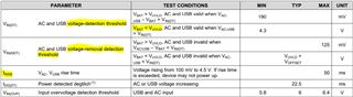
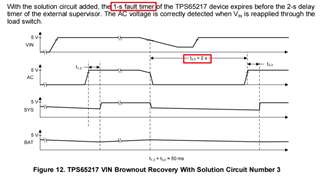
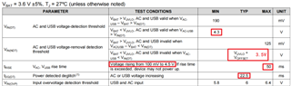
     1. AC rise needs to rise above 4.3V within 50mS

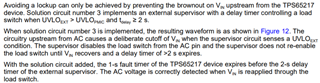
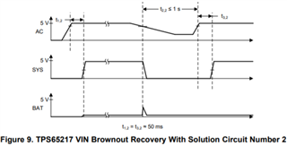
     2. After the AC rises to 4.3V, after 22.5mS, it will check again whether the AC reaches 4.3V (deburring detection). If it is, the AC will be selected as the power supply to SYS, and the power-on sequence will start.

     3. After the AC rises to 4.3V, if it drops below 3.5V, it will enter the LOCK state

Is my understanding correct? There are doubts here

    1. Is there any requirement for the rising waveform of AC within 50mS? For example: Is it allowed to rise, fall and then rise before 4.3V?

    2. For deburring detection, is the judgment standard for the second detection 4.3V or 3.5V?

    3. If it drops to 3.5V before deburring detection, will it also enter the LOCK state

Bset wishes

  • (Yellow AC input  Green SYS  output)

    Power supply KXN-305D: cannot start normally when the power supply is set to 4.6V

    Power supply KA3005P: start normally when the power supply is set to 4.3V

    Power supply KXN-305D: start normally when the power supply is set to 4.7V

  • Hi Felix,

    Thanks for reaching out! I have reviewed the waveforms provided in the previous message and it seems like something is pulling the AC signal below below the "voltage-removal detection threshold" (UVLO+OFFSET = 3.3+0.2=3.5V) during power-up. Could you provide the following information:

    • You mentioned USB is connected to GND. What about the battery pins (BAT, BAT_SENSE, TS)? How are those connected?
    • What is the capacitance on AC and SYS pins? Could you also provide the part numbers for these capacitors?
    • Have you implement any of the solution circuits in the brownout report? Designing Robust TPS65217 Systems for VIN Brownout
    • Have you compare your design with our guidelines in the schematic checklist?  TPS65217x Schematic Checklist (Rev. C)
    • What is the TPS65217 full orderable part number you are using?

    For reference, here is the spec for the pawer path detection limits:

    Thanks,

    Brenda

  • Hi Brenda

    Thank you for your response!

    Sorry this picture depicts wrong, this can't be started

    1.BAT, BAT_SENSE are shorted and connected to GND through a 10K resistor

    2.using ceramic capacitors,part number

    3.YES Except these 22uF

    4.yes checked

    5.TPS65217CRSLR

    I hope to know the specific AC requirements of TPS65217 from the moment of power-on to 22.5ms. The manual does not describe it in detail enough.,Hope to get answers to these questions

        1. Is there any requirement for the rising waveform of AC within 50mS? For example: Is it allowed to rise, fall and then rise before 4.3V?

        2. For deburring detection, is the judgment standard for the second detection 4.3V or 3.5V?

        3. If it drops to 3.5V before deburring detection, will it also enter the LOCK state

    best wishes

  • Replenish  10uF  part number:CL10A106KP8NNNC(SAMSUNG)

  • Hi Felix,

    We recommend 22uF cap in the SYS pin. Is your design based on the BeagleBone Black with the brownout solution circuit added? The spec parameters that defines SYS during power up are the voltage-detection threshold, the rise time and the power detected deglitch. If the voltage on AC studently drops during power-up before reaching the detection threshold (4.3V), this could affect the rising time causing the signal to exceed the 50ms rise time. The last scope capture you shared doesn't show a brownout issue because you are able to get a voltage on the SYS pin coming from AC (PMIC doesn't experience lockup). Could you provide a clear scope capture (where I can see voltage and time scale) showing AC, SYS, VIO and and VLDO1? Are you supplying VIO with the PMIC VLDO1 or an external regulator is being used?

    For your reference, the voltage threshold that matters during power-up on AC is 4.3V. Once it exceeds 4.3V, the voltage threshold that matters when the voltage drop is UVLO+OFFSET.  

    Thanks,

    Brenda

  • Hi Felix,

    We recommend 22uF cap in the SYS pin. Is your design based on the BeagleBone Black with the brownout solution circuit added? The spec parameters that defines SYS during power up are the voltage-detection threshold, the rise time and the power detected deglitch. If the voltage on AC studently drops during power-up before reaching the detection threshold (4.3V), this could affect the rising time causing the signal to exceed the 50ms rise time. The last scope capture you shared doesn't show a brownout issue because you are able to get a voltage on the SYS pin coming from AC (PMIC doesn't experience lockup). Could you increase the capacitance on SYS to 22uF and provide a clear scope capture (where I can see voltage and time scale) showing AC, SYS, VIO and and VLDO1? Are you supplying VIO with the PMIC VLDO1 or an external regulator is being used?

    For your reference, the voltage threshold that matters during power-up on AC is 4.3V. Once it exceeds 4.3V, the voltage threshold that matters when the voltage drops is UVLO+OFFSET.  

    Thanks,

    Brenda

  • thanks for the reply

    1.“”the voltage threshold that matters during power-up on AC is 4.3V. Once it exceeds 4.3V, the voltage threshold that matters when the voltage drops is UVLO+OFFSET. “”  GET!

    2.Tried adding 22uF to SYS, but it didn't work

    3.use PMIC VLDO1 Provide 1.8V to VIO

    4.I am going to add “brownout solution circuit”  But I have a question, the voltage detection threshold of the reference circuit is 4.0V, and the power-on threshold of the PMIC is 4.3, which will cause that if the voltage rises to 4.2V, neither the PMIC nor the anti-power-down circuit can function. What is the reason for this design?

  • Hello Felix,

    We may have some delays due to poor weather and potential power outages in Dallas. Hopefully we can respond by Friday but it may be as late as Monday. Apologies for the delay. 

    Regards,

    Alex

  • Hi Felix,

    If you have an application without battery, where VIO is supplied by VLDO1 (from the PMIC), then you can implement the solution circuit number 2 in the brownout report (Designing Robust TPS65217 Systems for VIN Brownout). You could also add the supervisor + load switch to the AC pin. To understand the solution circuit, please keep in mind the Brownout issue is all about input voltage dropping during operation. It doesn't really relate to power-up. The idea of implementing a supervisor+load switch is to prevent a brownout on the PMIC by detecting a UVLO ahead of time. That's why the UVLO on the external circuitry has to be higher than the voltage-removal detection threshold on the PMIC so it can disconnect the external source before UVLO condition is detected on the AC pin.    

    which will cause that if the voltage rises to 4.2V, neither the PMIC nor the anti-power-down circuit can function

    Not sure if I understand this last comment but 4.2V during power-up doesn't mean anything for the PMIC. Just for your reference, the table below shows the threshold voltages for the supervisor that is recommended on the brownout report.

    https://www.ti.com/product/LP3470A

    Thanks,

    Brenda

  • Thank you for your reply, because I was on vacation a few days ago, the reply was not so timely

    To understand the solution circuit, please keep in mind the Brownout issue is all about input voltage dropping during operation. It doesn't really relate to power-up. The idea of implementing a supervisor+load switch is to prevent a brownout on the PMIC by detecting a UVLO ahead of time. ” GET

    Let me sort it out, in the case of using only AC as input
    1. AC input is greater than 4.3V


    2. Delay 22.5mS to check again whether the AC input is greater than 4.3V


    3. If it is still greater than 4.3V, use AC as input, after a period of time (about 30mS) SYS output


    4. After that, as long as the AC is greater than 3.5V, the PMIC can work normally without entering an abnormal state (only focus on the power supply here)


    5. If the AC drop is lower than 3.5V, delay 4~6mS to check whether it enters the UVLO state again


    6. It is necessary to ensure that the drop time is greater than 1S to ensure entering the PRE OFF state


    Do you see if the above understanding is correct?

    One more question, is it allowed to go below 4.3V or lower between the first time greater than 4.3V (step 1), and between 22.5mS (deglitch detection) (step 2)?

  • There is no USB or BAT power supply in my system, so how long does it take for the AC input to be turned off here? After the AC input is turned off, VIN is greater than 4.3V for more than 100ms, and the AC is turned on again. Is there any risk in this design?

  • Hi Felix,

    Below is my feedback to your questions. The remaining items you listed above are correct. 

    After that, as long as the AC is greater than 3.5V, the PMIC can work normally without entering an abnormal state (only focus on the power supply here)

    Yes, but but to be more clear I would replace 3.5V with "UVLO+OFFSET". UVLO is a threshold that can be re-programmed on the EEPROM. If it is 3.3V, then the voltage-removal detection threshold would be 3.5V. As an additional note, the UVLO accuracy is +/-2%. 

    6. It is necessary to ensure that the drop time is greater than 1S to ensure entering the PRE OFF state

    This PMIC (TPS65217) has a 1 second fault times after it exit the Active state. If the supply at the AC pin drops below UVLO, it must be kept low for >1s (at least 2s recommended) before it recovers to make sure the voltage recovery is detected. This is the reason why the brownout report recommends a load switch+supervisor.  

    One more question, is it allowed to go below 4.3V or lower between the first time greater than 4.3V (step 1), and between 22.5mS (deglitch detection) (step 2)?

    It shouldn't be "allowed" for any input supply to studently drop and recover during power-up. This would indicate there is an issue happening with the external pre-regulator that is connected to the PMIC. The 22.5ms power detection deglitch is a typical (TYP) value in the spec. If the supply connected to AC drops below UVLO+OFFSET during power-up (after reaching 4.3V and before the detection deglitch which could be a littler higher or lower than 222.5ms) it will most likely not be detected as an undervoltage lockout. 

    how long does it take for the AC input to be turned off here?

    Not sure if I understand this question. How long does it take to turn OFF the AC input? This is controlled externally. It will depend on how fast the external supply drops and the input capacitance. If you have additional external components between the supply and AC pin (i.e load switch+supervisor) then it will depend on the timing parameters of those ICs.

    If your question was how long it takes to turn OFF the PMIC, there is a wait time of at least 1s from Active to OFF state.  

    After the AC input is turned off, VIN is greater than 4.3V for more than 100ms, and the AC is turned on again. Is there any risk in this design?

    This is OK. If you will be implementing the supervisor+load switch, I don't see any issues with enabling the load switch (to connect VIN to AC) 100ms after VIN is 4.3V as long as the AC pin is kept low for >1s when it drops below the removal-detection threshold. 

    Thanks,

    Brenda

  • HI Brenda
    My usage scenario does not require the use of batteries, which corresponds to case A in the slva901.pdf document, and the solution for adding load switches is for case B and C. I understand that in the case of no battery power supply, as long as the AC is powered off When it reaches 0V, the PMIC can return to the default state of unpowered, no need to use the load switch to delay more than 2S to avoid entering the BAT power supply mode

    In addition, amend my own description of the steps above. For power-on ramp-up, the manual requires 4.5V instead of 4.3V.

  • there is a wait time of at least 1s from Active to OFF state.

    I tried to search for the source with 1S in the TPS65217 data sheet, but I didn't see the description of this piece, can you tell me which manual it is on which page, thank you very much

  • Hi Felix,

    Here are the responses to your questions in the last two messages above:

    My usage scenario does not require the use of batteries, which corresponds to case A in the slva901.pdf document, and the solution for adding load switches is for case B and C. I understand that in the case of no battery power supply, as long as the AC is powered off When it reaches 0V, the PMIC can return to the default state of unpowered, no need to use the load switch to delay more than 2S to avoid entering the BAT power supply mode

    Yes, your application/scenario corresponds to CaseA. As I mentioned before, since you are already using the AC pin to supply the PMIC, solution circuit 2 would be the right one to implement. If you also wanted to add the load switch+supervisor to the solution circuit 2, that would be perfect. It will not affect the solution but instead will add more reliability to the system by isolating the AC supply for >1s in the case of an UVLO event. Below is the waveforms for solution curcuit#2. As you can see, it helps to make sure the voltage on the SYS pin reaches 0V after an UVLO event. If you add the load-switch+supervisor, the voltage on the AC pin will fully drop to 0V and will keep it low for >1s. 


    In addition, amend my own description of the steps above. For power-on ramp-up, the manual requires 4.5V instead of 4.3V.

    The comment you saw in the datasheet "Voltage rising from 100 mV to 4.5 V" is just a test condition used to test the rise time parameter. 


    I tried to search for the source with 1S in the TPS65217 data sheet, but I didn't see the description of this piece, can you tell me which manual it is on which page

    The 1s wait is specified in the device functional modes in the datasheet as in the Brownout report.

    From Brownout report:

    From Datasheet:


    I also wanted to highlight the following information about the UVLO register setting to make sure it wasn't overlooked when reading the Brownout report. For applications without battery we recommend adjusting the UVLO threshold (register 0x18 / bits 1:0) from the default (3.3V) to the lowest value (2.73V). 

    Thanks,

    Brenda

  • Thanks again for your reply

    A.As shown in the waveform diagram you provided, the load switch circuit is in the state of undervoltage. If I use the MOS switch to turn off the only power input: AC, the PMIC has no power supply at this time, why does it take 1S? What I mean is that the premise of the state diagram of the manual is that there is at least one power supply path for the device, and if I turn it off by means of the MOS tube switch, I no longer need to wait for the time in the state diagram for 1S, I don’t know if I do this understand correctly

    B.Regarding the setting of UVLO, it will be as low as 2.73V, there are doubts about the purpose of this setting,
    1. Because the voltage detection chip we selected externally is 4.0V, what is the meaning of setting lower than 3.5V here?
    2. When set to 2.73V, the output of PMIC has a channel of 3.3V. If the voltage does drop to 2.8V, the 3.3V output may be abnormal at this time, which is not needed.
    3. This seems to want to set the UVLO in the direction that it does not work as much as possible, and isn't the UVLO itself to protect against undervoltage conditions?

    Thank you for your patience,All the best

  • Hi Felix,

    From your previous messages it seems like solution circuit#2 and solution circuit#3 from the brownout report are getting mixed. Please note that solution circuit#2 is the one that better matches your system needs because you are not using a battery and VIO is being supplied by the PMIC VLDO1.

    The supervisor + load switch is present in the solution circuit#3 because when the AC voltage goes below UVLO the PMIC is still connected to the BAT voltage as well as the external regulator supplying VIO.  

    What will happen if all the power sources (including BAT) are removed from the PMIC? It will just shut down. The 1s wait time would not be applicable. See a capture of the global state diagram below. Just like I mentioned before, if the supervisor + loadswitch is added to any of the solution circuits it will not have any negative effect on the PMIC response. It will just hold the AC pin low for a time period configured in the external ICs. 

    Regarding your question on the UVLO setting, TI recommends adjusting the UVLO of the TPS65217 device to the value required by the chemistry of the battery used. When a battery is not present, the lowest UVLO voltage reduces the chances of a brownout condition occurring. If your application does not use a battery, then the lowest UVLO (2.73V) would be the right setting. If a supervisor + load switch was integrated in your solution circuit, the UVLO detected by the external ICs doesn't necessary need to be 4V specifically. It just needs be higher than the UVLO+OFFSET in the PMIC. 

    Thanks,

    Brenda

  • Thank you Brenda for being very patient and answering my questions, thanks