Hi Sir
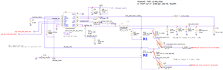
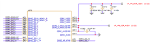
TPS54325 is applied to the power supply of MAC 1.0V 1.6A (when the power supply is tested, the MAC chip is not installed), the electrical conditions are as follows~~
Input : 12V
Output : 1.0V / 1.6A
Cff: 22pF change to 560pF
R123 : 7.15k change to 30.9k
R137 : 22.1k change to 100k
C1033 : POSCAP 470uF change to MLCC 1206 22uF 6.3V
C131 : POSCAP 470uF change to MLCC 1206 22uF 6.3V
L7 : 1.5uH change to 1.0uH
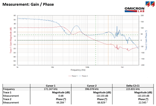
We tried to increase the cff capacitor and reduce the output capacitor value to open the phase margin to more than 45 degrees.
But the increase of cff is very large, and the bandwidth has exceeded 1/5 of the switching frequency.
Is there any doubt that the control system is unstable?
We have used a lot of TPS54X25 in more than a dozen related circuits, but have never seen Cff increase so much that the phase margin can be greater than 45 degrees.
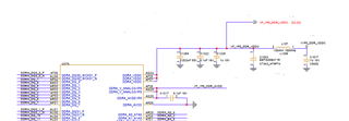
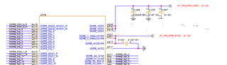
The load we added is at the near end of the POL, but the output power supply path has been changed three times via the pcb layer to the Net1/Net2/Net3 area ten centimeters away. Could this be the main reason?
Differences in bode plot before and after parameter change of circuit parts
Before
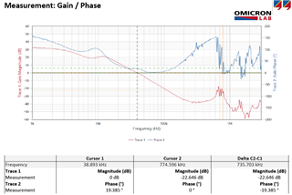
After