This thread has been locked.

If you have a related question, please click the "Ask a related question" button in the top right corner. The newly created question will be automatically linked to this question.

TPS61023: Discharge Supercapacitor

Part Number: TPS61023
Other Parts Discussed in Thread: TPS61094

Hi,

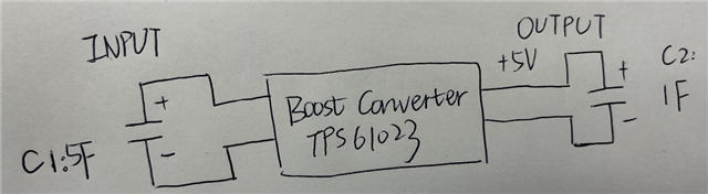
I am using TPS61023(Adafruit) to boost the voltage from a super capacitor with high farad to charge another super capacitor with low farad. The diagram is as follows.

From TPS61023's datasheet, the boost converter should be able to be activated at 1.8V and discharge supercap until 0.5V.(Am I right?) 

At the beginning, C1=3V, C2=0V. Finally, C1=1.28V, C2=3.55V.  My question is, why can't the boost converter discharge C1 until 0.5V? When I remove C2, and use a multimeter to test the open-circuit output voltage of the boost converter, the output voltage is~5V. Why can't the 5V boost converter output charge the 3.55V C2?

If TPS61023 is not a good one for my system, can you recommend some other options?

Thank you! I appreciate your help!

  • Hi Xiaoying,

    1F capacitor can be too large for TPS61023. And if you charge supercapacitor directly with TPS61023, it will enter current limit. How about TPS61094? It is designed for supercapacitor back up application.

    -Wenhao

  • Hi Wenhao,

    Thank you for answering. But I still not quite understand-- the charging current should be the largest at the beginning. C2 can be charged very quickly to 3.55V. There are still energy in C1=1.28V, and the boost converter is still working. Why can't it charge C2 more? How to discharge C1 to 0.5V? 

    Thanks!

  • Hi Xiaoying,

    Would you mind sharing me some waveform you took for the test? What is the input voltage, output voltage when TPS61023 is charging supercapacitors? Anyway, TPS61023 is not a good choice for this application. You may take a look at TPS61094.

    TPS61023 has built-in soft start mechanism. It does not have full current capability at beginning. Before output voltage rises to input voltage, it enters pre-charge phase. It uses its high side PMOS and acts like LDO to charge output capacitor. Therefore, output current capability is limited and its efficiency is very low because much of voltage drop happens at high side FET. After output voltage reaches to input voltage, it starts to switching with enhanced load capability.

    The efficiency when TPS61023 is in pre-charge phase is low. The energy of your C1 will dissipate a lot at pre-charge phase and may result in TPS61023 thermal shutdown. The maximum recommended output capacitance for TPS61023 is 1000uF. 

    BTW, it is good to know why you have supercapacitor at both input and output side? Would you please give more information about your application? If it is for backup power, why output also has caps?

    -Wenhao

  • Hi Xiaoying,

    Any feedbacks?

    -Wenhao

  • Thanks for your reply. I think you are right. I am still investigating the circuit.

  • Hi Xiaoying,

    I close this thread. If you have more questions, you could still ask below.

    -Wenhao