This thread has been locked.

If you have a related question, please click the "Ask a related question" button in the top right corner. The newly created question will be automatically linked to this question.

BQ24179: Custom Board: Battery Not Charging

Part Number: BQ24179

Hi,

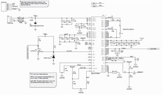
I designed a custom board with BQ24179 to manage a 4S1P LiPo battery. A few weeks ago, I received my five sample boards. Four out of five boards work as expected. But one of them does not charge a battery. Since all the boards have the same design, I can't figure out why one of them isn't working as expected. I have attached the charger schematic below.  

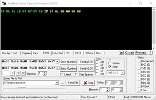
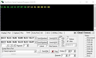
I can communicate (In my design I use level shifter and UART-to-I2C bridge IC to communicate with the charger) with the board and listed below is charger status and fault data:

Charger Status 0: 0x2F (Looks good - problem here)

Charger Status 1: 0x6A (Bits 5-7 show me that the charger is in FAST CHARGING (CC mode) but it isn't charging)

Charger Status 2: 0x01 (Everything is normal)

Charger Status 3: 0x00 (Everything is normal)

Charger Status 4: 0x00 (Everything is normal)

Fault Status 0:      0x03 (VAC1 and VAC2 are in overvoltage protection. But this shouldn't stop it from charging the battery. I get the same error on other boards as well. ASIDE: how to get rid of this error?)

Fault Status1:       0x00 (Everything is normal)

Shown below is the same data (in yellow) captured with the RealTerm serial terminal.

In addition, the V_TS is 2.91V. If you require additional information, let me know.

Regards,

PB

  • Hi PB,

    Input overvoltage on VACx and/or VBUS turns off the converter so no charging.  The default OVP is 7V on this device.  You need to change the setting in REG0x10 bits 5:4.

    Regards,
    Jeff

  • Hi Jeff,

    I changed the VACx OVP to 22 as my input voltage is 12.25V. The VAC overvoltage protection errors are gone but the battery is not still being charged. I have tried different batteries just to make sure it's not because of the battery. Please find attached charger status and fault data.

    Let me know if you need to see additional data.

    Regards,

    PB

  • Hi Jeff,

    After further investigation, I know why one of the five boards isn't charging the battery. 

    It's because BQ24179 isn't switching.  First, I tapped into SW1 with an oscilloscope. I get a constant voltage reading of approximately 12V (The input supply is 12.25V). When I tap into SW1 of a working board, I see switching happening. 

    Second,  I measured diode voltage drops across Q1 (SW1 to PMID) and Q4 (SW2 to SYS). The voltage drops across Q1 and Q4 are 0.009V and 0.428V, respectively. This shows the Q1 MOSFET isn't working. As a result, BQ24179 isn't switching and charging the attached battery. 

    Lastly, my question to you based on your experience is how common is it to get a non-functional integrated MOSFET in BQ24179?  The main reason I selected this IC is that it is fully integrated (i.e. powerpath capability, buck-boost functionality, etc.). My plan for this non-working board is to rework the board and test if it works with a brand new BQ24179. 

    I thought this information may be useful for you and the people on this forum. Thank you so much for your time. 

    Regards,

    Paul

  • Hi Paul,

    Q1 only sees VBUS (unless Q4 is damaged).  Is it possible that you hotplugged into VBUS and the ringing went outside the abs max ratings, either overshooting or undershooting?  If so, then you might need an input snubber consisting of a small 1-2.2ohm power resistor in parallel with a 1-2.2uF capacitor.

    Regards,

    Jeff