This thread has been locked.

If you have a related question, please click the "Ask a related question" button in the top right corner. The newly created question will be automatically linked to this question.

SG3525 SMPS 0-30v , 0-5A switch power supply

Other Parts Discussed in Thread: TL494

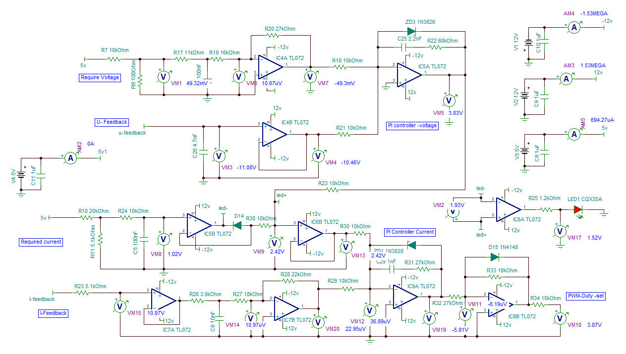
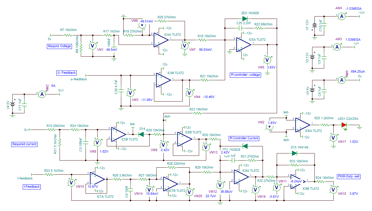
I recently read a paper which is the Laboratory switching power supply 0-30 V 0-5 A  in which the regulatory structure described the voltage loop and current loop that could control the output voltage from 0v to 30V and the output current from 0A to 5A. Actually I did not fully understand these control circuits , so hope to get your assistance.

 There are my understanding and queries below:

  1. Could the control circuits continuously to adjust the output voltage and current by P1(required voltage) and P2 (required current) respectively ? Are they independently controlled ?
  2. About the required voltage and U-feedback.  The output voltage should be sampled at u-feedback from resistive divider. If the output voltage can be adjusted by P1 , the u-feedback should be follow the p1 voltage value ,right ?   In additional , the R18/ R21 are a summing networks, that and IC5A are consist of a inverting summer with PI controller. I confused how the u-feedback can be synchronously changed by adjusting  the P1 ( means the voltage of u-feedback equal to voltage of P1 adjusted) ?  Might the IC4A, IC4B and IC5A be merged an error amplifier ?
  3. About the required current and I-feedback. The R30 and R29 are a summing network, that and IC9A are consist of a inverting summer with PI controller. The same reasons I still confused how the I-feedback can follow the P2 value ? but I can understand the p2 can limit the output current that means  the PWM-duty will be decrease until turning off the main control chip(sg3525) if the output current is more than the P2’s limited value ,right ?.
  4. About the PWM_duty_set. Could P1/P2 (required voltage/current ) adjusted synchronously change the PWM_duty ?

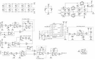
 The attachments are circuit diagrams for your reference.
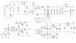
 Best Regards,

 John

  • Hi John,

    1) Yes, P1 controls output voltage.  P2 sets a clamp to limit the current.

    2) Yes, U-feedback should follow P1 setting.  R18/R21 are inputs to an inverting, summing op amp where V(-) is at virtual ground.  IC4A, IC4B, and IC5A could be merged into a single amplifier, but the P1 setting would have to be moved to the V(+) pin and you'd have to make sure the transfer functions from both inputs are balanced.

    3) I-feedback does not follow the P2 value.  P2 sets a limit.  If current is low P2 clamp is inactive.

    4) P1 will control the duty cycle.  P2 will set a maximum value for the duty cycle.

    Regards,

    Eric

  • Hi Eric,

    Thanks for your analysis.

    1. I see the point 1 , 3 and 4. 

    2. About the point 2, I still could not clear how the u-feedback follow the P1 setting. In additional, you mentioned " the P1 setting will have to moved to the V(+) pin" that means the sum (R18/R21) will be double IC4A  input (2*p1 setting), right ? 

    I could not sure whether I understand your means, however, I did two type of circuit simulations , one is original , another is one updated ( P1 setting move to V(+)of IC4A) such as the attachments.

    simulating original circuit diagramsimulating updated circuit diagram

    According to the circuit simulation, the u-feedback could not follow the P1 setting. I don't know what went wrong.

    Best,

    John

  • About #2.  In the original circuit Required Voltage passes through IC4A, which is an inverting amplifier.  So the Command to IC5A is a negative voltage to the (-) pin which produces a positive voltage out of IC5A.  Meanwhile the U Feedback passes through a unity gain buffer, IC4B, to the (-) pin of IC5A, which produces a negative voltage out of IC5A.  At the output if IC5A you have, neglecting gains, Required Voltage - U Feedback.  This is the basic premise of a control loop.

    This function could be done in 1 amp with the right configuration.

    Regards,

    Eric

  • Hi Eric,

    I guessed the designer of original circuit  want to make the IC5A output =0 , namely making " - IC4A + IC4B = 0"  or say making "u-feedback = required voltage" , but there is no finding feedback loop among  IC4A,IC4B and IC5A , so actually the u feedback could not follow the voltage setting, right?  

    in additional ,the  Pin1 , Pin2 and pin9 in SG3525 are an error amplifier and there is a feedback loop between Pin1 and pin9 . So,the pin1 can follow the pin2.  If the u-feedback connect to pin1 , the output voltage can be changed by adjustabing pin2 voltage from 0.6v~3.6v, but the output voltage can be adjusted to 0V , because the sg3525's output B and output A  will be turned off  when pin2 voltage lower than 0.6V.

  • Hi John,

    Your questions are related more to general op amp and control theory.  I was happy to help you get started but cannot continually answer questions if they are not related to the operation of one of TI's regulators/controllers.

  • Hi Eric,

    Could  you recommend a design scheme about  adjustable output voltage and current with sg3525?

  • Hi John,

    I'm not aware of any voltage/current adjustable designs.  Our customers design circuits tailored to their specific application.  Meaning they have fixed output voltages and a maximum expected current for their end product.

    The SG3525 is a legacy regulator so you won't find a lot of support collateral.  For the newer products we have reference designs and simulation tools.  For example, the TL494 is similar to the SG3525 and would be a good starting point.  Find the TL494 home page here

  • Hi Eric,

    Do the simulation tools include TL494 OR SG3525 ? Could you recommend the simulation tools  to me ?

    thanks,

    John

  • Hi John,

    TI does not have a spice model for the TL494.  We do have at least 2 excellent Application Notes dedicated to designing with the TL494.  They are on the home page (link above).  In addition to the data sheet, the App Notes from 2005 and 2014 look very detailed.

    If you Googe TL494 spice model you will find a lot of results.  This is a popular, legacy part and I see many people using LT Spice and TL494 models from various third parties.

    Regards,

    Eric