


Hello,
I'm having a problem with a product in the field. A review of the schematic brought up a question about the TL431AIDBZ I am using. Here is the schematic:
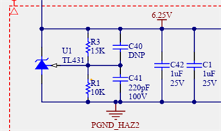
There are additional capacitors elsewhere in the circuit from U1 cathode to anode that bring the total load capacitance (including C1 and C42 shown) to 5.2uF.
One theory for the product problem is that the 6.25V regulated by the TL431 is drooping (possibly due to EMI). We saw the 6.25V drooping in response to an EMI event during product testing. Adding C41 helped eliminate the drooping, so it was added as a change to the product. At the time we saw the drooping, R3 and R1 were also significantly higher and reduced to the values shown as part of the fix.
However, the TL431 datasheet does not have any information about placing a capacitor from the Vref pin to the anode and there is concern that it could be part of the problem with our product in the field. Does having a capacitor on the TL431 reference pin to anode (C41) cause any problems like instability or other undesired effects? Should the capacitor be constrained to a certain value range?
I know from testing that as I increase C41 the noise of the 6.25V node increases. This makes sense because it slows the feedback to the TL431. I am happy with the 6.25V noise with C41 at 220pF. Any information on the effects of C41 (negative or positive) would be appreciated.
