This thread has been locked.

If you have a related question, please click the "Ask a related question" button in the top right corner. The newly created question will be automatically linked to this question.

TPS61160A: Inductor and output capacitor setting

Guru 19575 points
Part Number: TPS61160A

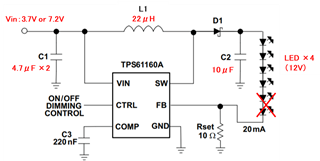
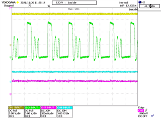
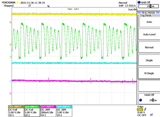
On 5.3Vin → 12Vout / 20mA condition for TPS61160A, L: 20μH and Cout: 10μF become unstable and L: 10μH and Cout: 1μF become stable.

Please let me know about two points below;

①is there calculation method for internal loop compensation? 

②Are high L and Cout value have any condition for voltage / current spec?

I hope to decide 20μH or 10μF (or both) suitable or not for above condition. 


Best regards,

Satoshi

  • hi satoshi

        Can you help firstly clarify the unstable phenomenon?

        Normally the output cap is related to ESR zero while inductance is related to the right half phase zero. 

  • Hi Wang,

    Thank you for reply,

    ・Schematic is attached below;

    ・About unstable phenomenon, FB line add 10kHz oscillation and a little voltage degrease. 

     Higher Vin become higher 10kHz oscillation.

     I'm concern about two points below;

     ・Control dimming is 225kHz, over recommend range.

      When PWM change to 90kHz, 10kHz oscillation was not found.

     ・IC board to LED board are connecting 110mm cable.

    ・When L and Cout changed L: 10μH and Cout: 1μF, 10kHz oscillation almost invisible.

     But V_FB on 7.2Vin is a little decrease. 

     Waveform are attached below;

     ※Yellow: V_LED, Green: V_SW, Blue: Vin, Purple: V_FB, Duty: 100%

    Vin: 3.8V                         Vin: 7.2V


     Sorry, test data for L: 22μH and Cout: 10μF are nothing left.

    Please let me know additional question below;

    ①Is there possibility to relation for high PWM frequency and oscillation (or noise) for feedback line?  

    ②Is there condition for cable length the LED and feedback line / board?  

    ③If there any measure for reduce10kHz oscillation, please let me know.

    Best regards,

    Satoshi

  • Hi satoshi

       1. Is the system always unstable when frequency is larger than 100kHz? As 252kHz is quite near the switching frequency 600kHz, it is very likely to influence normal operation if layout is not proper.

       2. it is recommended that the trace or cable connecting FB is as short as possible.

       3. right now not sure the root cause of unstable condition, the items mentioned above can either or both contribute this. Decreasing of L and C will increase the bandwidth of the system and is beneficial to decrease oscillation