This thread has been locked.

If you have a related question, please click the "Ask a related question" button in the top right corner. The newly created question will be automatically linked to this question.

TPS6594-Q1: TPS65941x + LP8764x PMICs

Part Number: TPS6594-Q1
Other Parts Discussed in Thread: TPS6594EVM

Hello TI Team.

We are following PROC105E5 in our design and want to check some function of TPS6594-Q1.

Q1: The flag should become 1 when UV/OV/ILIM happen but register values are still 0.

overcrurrent the BUCK1 to 5A but 0x5C flag doesn't change.

Q2: Why EN_DRV(0x80、0x82) can’t be modified?

Q3: How to check and verify Q&A Watchdog communication?

Thanks and best regards,

Tommy

  • 1. From your register read out, the current limit interrupt is masked. Register 0x49 reads 0xBB. The interrupts will not fire while masked.

    2. To control EN_DRV pin, you must have the Watchdog fully disabled and have the ESM enabled for SOC or MCU. Other option is to have Watchdog fully enabled.

    I'll let colleague follow up on your Watchdog communication question.

  • Hello,

    The watchdog communication is described in the datasheet, https://www.ti.com/lit/ds/symlink/tps6594-q1.pdf#page=100 . 

    Please be advised if you configuration uses the DISABLE_WDOG pin (GPIO8 of TPS6594-Q1) to set the WD_PWRHOLD bit.  The initial 4 answers will transition the PMIC watchdog out of the long window and the second 4 (correct) answers will result in the WD_FIRST_OK bit being set.

    If you are using the TPS6594EVM, then consider using the watchdog page in the Scalable PMIC GUI.

    Regards,

    Chris

  • ->1.I can read the 0x5C after change 0x49 Register value. Thank you.

    ->2.To control EN_DRV pin, you must have the Watchdog fully disabled and have the ESM enabled for SOC or MCU.

    The register 0x80 can't be modify after I have the Watchdog disabled by pulling high GPIO8 of TPS6594 to 3.3V.

    How to check ESM enable for SOC or MCU?

  • Watchdog function register(0x401~0x40A)

    0x401~0x40A are in the address 0x4C?

  • 0x401~0x40A are in the address 0x4C?

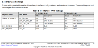
    If you are using the TPS65941212EVM then the I2C2 address is 0x12.

    Page 0 -> 0x48

    Page 1 -> 0x49

    Page 2 -> 0x4A

    Page 3 -> 0x4B

    Page 4 -> 0x12

    In the PDN solution, https://www.ti.com/lit/ug/slvuc32b/slvuc32b.pdf#page=21

    Also the I2C2 is physically located on GPIO1 and 2 for this configuration.  

    Whenever the I2C2 functions are enabled on GPIO1 and 2 then the PMIC will use I2C2 for the PAGE 4.  If not then I2C1 is used.

    Regards,
    Chris

  • Hello,

        I would recommend disabling both the watchdog and the ESM to test the EN_DRV.  The ESMs are disabled by default.  When the nRSTOUT pin goes high, the value of GPIO8 is latched in the the watchdog power hold.  Be sure that GPIO8 is high before the enable pin goes high on the PMIC.  Once disabled you should be able to control the EN_DRV pin.  

    Regards,

    Chris