This thread has been locked.

If you have a related question, please click the "Ask a related question" button in the top right corner. The newly created question will be automatically linked to this question.

LM138: 5A constant current over a long cable.

Part Number: LM138
Other Parts Discussed in Thread: LM1084, LM317

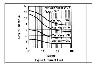
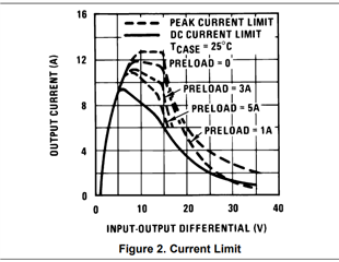
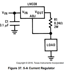
I need to have a 5A constant current and I am thinking of using the circuit in Figure 37, input voltage is ~28V.   My load is quite far a way at the end of a cable (say 100ft).   Can the LM138/38 capable of driving such a long cable assuming the voltage drop over the cable such that the voltage at the load is no more than 9V from the input???

(by the way, in your Figure 37, if it is a 5A constant current, shouldn't the Resistor power be much higher than 2W? V*I = 1.25V*5A = 6.25W ?)

thanks,

-Long

  • Hello Long,

                     I am looking into this, I will get back to you by the end of the day tomorrow. Thanks!

    Regards,

    Srikanth

  • Hello Long,

                      We would not recommend that you connect the load at such a long distance away from the OUT pin of the Regulator. The Regulator would see a lot of Inductance at the OUT pin for a 100ft cable, and at startup (or during changes in load) we can indeed expect a very large voltage spike that could very easily damage the part, especially at large load current like 5A. If the part survives the inductive spikes, it can continue to supply the load current, however, as you point out, the load will indeed receive a much smaller voltage drop. We strongly recommend that the load be placed as close to the OUT pin as possible. 

                       Yes, I would agree with you that the wattage of the resistor in Figure 37 should be much higher. Thanks!

    Regards,

    Srikanth

  • Hi Srikanth, thanks for the info.  In that case, is there another TI product or some other method that would allow me to achieve my design goal?  It seems to me like any design would see this high inductance load @ start up yes?  by the way, my load would just be an resistive load (like a 1Ohm resistive load for example).   Not sure that would change the recommendation since we would still have the long inductive cable in between.

    Would it help if we have a zener diode on the line/cable to clamp the initial spike?  (just a thought, assuming we could find one that works).

    regards,

    -Long

  • Hello Long,

                      The principle issue with the design is the power dissipated across the Die. With VIN = 28V, the voltage across the load being 5V (5A*1Ω), the drop across the cable being ~9V implies that the output voltage of the LDO is ~14V. The power dissipated across the device is ~70W ((28V - 14V)*5A), which is extremely large. Would it be feasible for you to connect the LDO closer to the 1Ω load end of the cable? If so, then the inductance issue would be bypassed and one possible solution would be to step down the Input voltage of 28V using a Buck converter and feed this voltage to the Input of the LDO. This  will reduce the input voltage (and power dissipation) of the LDO.

                       LM138 requires minimum dropout of 3V, which implies that the power dissipated across the device would be at least 15W (3V*5A). This is still way too large for this device. LM1084 requires 1.5V of dropout (significantly lower than LM138), and using the NDE package on a board with good layout and using heatsink(s) after stepping voltage down with a Buck converter, it may be possible to dissipate power while keeping the Junction temperature less than 125°C. Thanks!

    Regards,

    Srikanth   

  • hi Srikanth, I understand the info you provided above regarding the power dissipation and all but I'm a bit confused now of the capability of this part.  

    1) The part datasheet indicates that it is a 5A regulator and if a minimum of 3V drop is required, then regardless of any application or loads, the power dissipation is always at the minimum 15W (3V * 5A).   Can the part handle 15W of power dissipation?

    2) Figure 1 of the datasheet shows the current limit at different Vin-Vout.   Even at Vin - Vout = 10V (ie the difference between input and output is 10V), the output current is ~8A.   This is peak current @ roughly 100ms or so I guess it is NOT a constant current right?  Figure 2.0 seems to suggest it could be a 'sustained' current but can you confirm?  

    3) The application the I am considering is the Constant current as shown in Figure 35.   Since the regulator will do whatever it can to keep the Vout about 1.25V above the Vadj (across the R1v 0.24 Ohm resistor), can you let me know the Vout in this application?  (For two cases: load is next to R1 and load is far away from R1).

    ***[LN] In this case I think you're saying it would depend on my load and the drop across the cable, hence your answer above.  I think I get this point so you can ignore this question #3.  Thanks.

    ***I will take a look at the LM1084 datasheet.  Thanks!

    Q: Can I use LM1084 as a 5A constant current source in the same manner as the LM317? 

    Anyhow, I tend to agree with you that I need to lower the input voltage to reduce the power consumption but I need your clarification above.  

    thanks,

    -Long

  • Hi Long,

    Srikanth is out today. He will be back tomorrow to carry on the conversation. 

    Regards,

    Nick

  • Thanks Nick!  

  • Hello Long,

                      Please note that LM138 device is a relatively old device, we do not have much characterization data on this device. However, I think your guess is correct, LM138 cannot continuously dissipate 15W of power. The tests the figures refer to must have been performed by low duty cycle pulse testing to ensure that the Junction temperature remains less than 125ºC. 

                      For reasons mentioned in the previous post, I think you have a better chance with LM1084. This will still require a board layout with very good thermal dissipation and /or heatsinks. As also mentioned earlier, it would be better if the LDO could be connected at the load end of the cable. Thanks!

    Regards,

    Srikanth  

  • Thanks Srikanth, will do that.  Could you confirm if I can use LM1084 in the same manner as shown in Figure 37 of the LM138 datasheet?  I would assume so but just want to confirm.

    thanks!

  • Hello,

             Yes, LM1084 can also act as a current regulator in the same manner as LM138 in Figure 37. Thanks!

    Regards,

    Srikanth