This thread has been locked.

If you have a related question, please click the "Ask a related question" button in the top right corner. The newly created question will be automatically linked to this question.

BQ24780S: For BQ24780S, how to close the battery when ACIN is supplied?

Part Number: BQ24780S
Other Parts Discussed in Thread: BQ25720, BQ24780

Hi, Team,

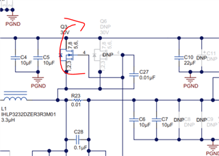
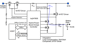
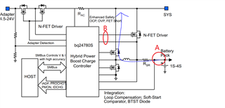
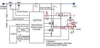
We are  using the 4S battery with the full voltage to 16.8V and need to close the battery when the 14V  ACIN is supplied.  We  prepare to change the BAT FET to the dual FET as the AC FET which will block the body diode current. But per our test , the BAT FET can not close when the 14V ACIN  is supplied untill the ACIN voltage rise to 17.8V.  How to modify the circuit?

Could you give some advise on it?

Best Regards,

Tiger

  • Hi,

    BATFET cannot prevent battery discharge current because it will go through the body diode even when it is closed.


    BQ24780S is a buck charger, the input is never supposed to lower than the battery voltage. It may be difficult to accommodate to all the operations if you continue down this path. For example, 14V input available, the BATFET turn off/switch over timing may be hard to achieve even if you add a dual blocking FETs. 

    I would recommend looking into the BQ257xx buck boost series.

    https://www.ti.com/power-management/battery-management/charger-ics/products.html#p273=Switch-Mode%20Buck-boost

    Thanks and I hope this helps,

    Peng

    *Please press "This Resolved My Issue" on the thread if my answer is satisfactory
     

  • Hi, Peng,

    Many thanks!

     The BQ257xx buck boost series is not suit for our application as the buck boost switching is allways on with too many noise.

    Please refer to the  7.3.2 System Power Selection   in the DS, in where list the condition of BATFET and ACFET on /off

    When the adapter is not present, ACDRV is pulled to CMSRC to keep ACFET and RBFET off, disconnecting the
    adapter from the system. BATDRV stays at V BATSRC + 6 V to connect battery to system if all of the following
    conditions are valid:
    1. V CC > V UVLO
    2. V ACN < V SRN + 200 mV
    3. ACFET/RBFET off
    After the adapter plugs in, the system power source switches from battery to adapter if all of the following
    conditions are valid:
    1. ACOK high
    2. Not in LEARN mode
    3. In LEARN mode and V SRN < battery depletion threshold

    It seems the key point is the   V ACN < V SRN + 200 mV which turn on the BATFET. How about to pull down the V SRN when the ACIN supplied? Thus the RES between the V SRN pin and the BAT must be change to 10k.  As the input impedence of V SRN should be high, it should make sense, right?

    Please help to comfirm it in detail!

    Best Regards,

    Tiger

  • Hi Tiger,

    I think it will be difficult to anticipate potential issues if your VIN is lower than battery voltage. For example:


    Even if the BATFET path is fixed, there is a path from battery -> inductor -> high side FET body diode back to the SYS input. The inductor is short at DC.

    Thanks and I hope this helps,

    Peng

    *Please press "This Resolved My Issue" on the thread if my answer is satisfactory

  • Hi, Peng,

    Many thanks!

    Is there any other part meet my requirement?

    1. When ACIN powering, cut the battery  ,no matter what the VAC is.

    2. AC or BAT dirrect power the system, no buck or boost involved.

    3. Support battery  charging

    Best Regards,

    Tiger 

  • BQ257XX buck-boost charge controller as previous suggested. BQ257XX can operate in Pass-Through-Mode (PTM) which offers 99% efficiency. 

  • Hi,Tiger Zhou, 

    Many thanks!

    But from the schematic of BQ25720 , the VSYS is also clamp by the BATFET body diode, so the battery can never be closed, right?

    We need the battery fully being close when the ACIN supplied regardless the voltage of the ACIN (range from 12-18V).

    How about  to add the N-FET between the battery and the Rsr and use the BATDRV signal to control it  in the old 24780 circuit? Thus we just need to close the  N-FET by short the Vgs when need to close the battey.

    Best Regards,

    Tiger 

  • Hi Tiger,

    For BQ25720, you don't need to add any additional circuits to do that.

    Please see below from datasheet: 

    "As the battery voltage rises above the minimum system voltage, system voltage is regulated 150 mV above battery voltage when BATFET is turned off (no charging or no supplement current)."

    When the system voltage is regulated 150 mV above battery voltage, the battery body diode will not discharge. 

    Thanks and I hope this helps,

    Peng

    *Please press "This Resolved My Issue" on the thread if my answer is satisfactory

  • Hi, Peng,

    Many thanks!

    We  need the AC or BAT dirrect power the system, no buck or boost involved to reduce the switching noise. So the BQ25720 might not suit for it.

    How about  to add the N-FET between the battery and the Rsr and use the BATDRV signal to control it  in the old BQ24780 circuit?

    Best Regards,

    Tiger 

  • Hi Tiger,

    In my opinion, BQ257XX buck boost controller is your best path forward. Many customers have used it in complicated and potentially sensitive applications.

    As I mentioned before, I do not recommend using BQ24780S with VIN < VBAT. Even if we ignore the BATFET modifications required (whether or not that is possible is another discussion), the high side switch path body diode cannot be fixed. Inductor is short at DC.


    Thanks and I hope this helps,

    Peng

    *Please press "This Resolved My Issue" on the thread if my answer is satisfactory

  • Hi, Peng,

    Many thanks!

    I saw the path in your circuit, but I means to add the N-FET in A point of my circuit and share the BATDRV with the existing BAT-FET. When the ACIN supplied, short the B point by a small P-FET  to close the BAT-FET. 

    Can it work? 

    Best Regards,

    Tiger 

  • Hi Tiger,

    I can only provide tips and recommendation. My recommendation is to use the BQ257XX buck boost controller.

    However, this is ultimately your decision. The support will be more limited as well if you went this route. This is also the first instance I see where someone try to do this.

    At the minimum, please modify the EVM and test it with the modification you plan to make first. We have never tested it in that configuration and we don't recommend it.

    https://www.ti.com/tool/BQ24780SEVM-583 

    Thanks and I hope this helps,

    Peng

    *Please press "This Resolved My Issue" on the thread if my answer is satisfactory

  • Hi, Peng,

    Many thanks!

    We just want no switching when in normal mode.

    Per my new circiut, there have a issue  when in charging mode , that as the N-FET added  is between the BAT and the charging FET and the BAT-FET is closed when charging, so there always have a body diode in series with the BAT, which will shift the end point of charging voltage. If we still set the charge voltage to 16.8V, the battery will never be full charged.  How to work around? Would like to have your advice.

    Best Regards,

    Tiger 

  • Hi Tiger,

    Please test an EVM. BQ24780S is not recommended for your application.

    https://www.ti.com/tool/BQ24780SEVM-583

    Thanks and I hope this helps,

    Peng

    *Please press "This Resolved My Issue" on the thread if my answer is satisfactory

  • Hi, Peng,

    Many thanks!

    We will try on the EVM. 

    Could you give some advice on how to compensate the charging voltage shift by the N-FET added  between the BAT and the charging FET?

    Best Regards,

    Tiger 

  • Hi Tiger,

    Our office is closed in observance the Presidents Day Holiday. We will get back to you by 02/23 after we return to the office.

    Best regards,

    Eric

  • Hi,

    There won't be any voltage shift because the voltage sense is done on SRN pin.

    Both NFETs should turn fully on and fully off at the same time. The source connection of the NFETs should be the same as well.

    *Note =With these type of applications, I am only answering questions and does not in anyway guarantee my comments/suggestions will work in these type of applications.

    Thanks and I hope this helps,

    Peng

    *Please press "This Resolved My Issue" on the thread if my answer is satisfactory

  • Hi, Peng,

    Many thanks!

    Please refer to the attached circuit, the added NFET is  for blocking the battery when ACIN supplied and the BATFET is closed when charging , so there should be a body diode in series with battery.. 

    Could you give some advice on how to compensate the charging voltage shift by the body diode of the N-FET added  between the BAT and the charging FET?

    Best Regards,

    Tiger 

  • Hi Tiger,

    Once again, I do not recommend BQ24780S for your application.

    Thanks,

    Peng

  • Hi, Peng,

    Many thanks for your kindly help!

    We will try on the EVM. 

    Best Regards,

    Tiger