This thread has been locked.

If you have a related question, please click the "Ask a related question" button in the top right corner. The newly created question will be automatically linked to this question.

TL5001A: inverter

Part Number: TL5001A
Other Parts Discussed in Thread: TL5001, MC34063A

Hello,

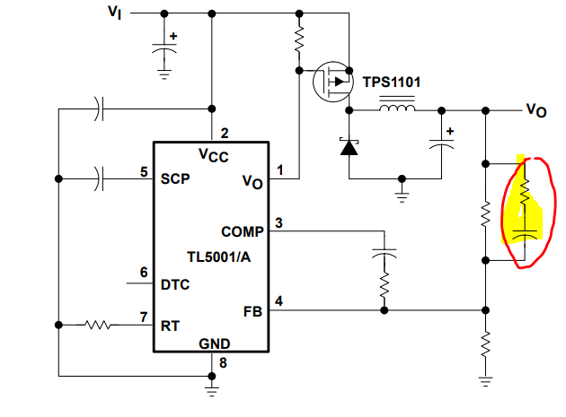
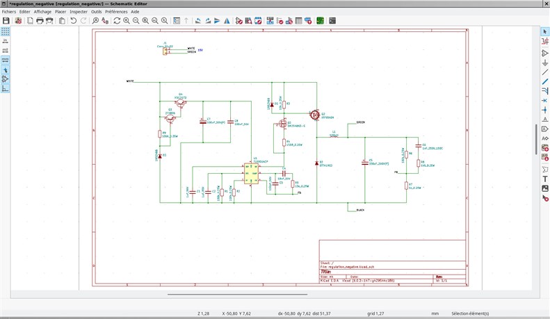
In a special power supply, I have to replace a transformer by another subcircuit to create a negative polarization (-100Vdc).

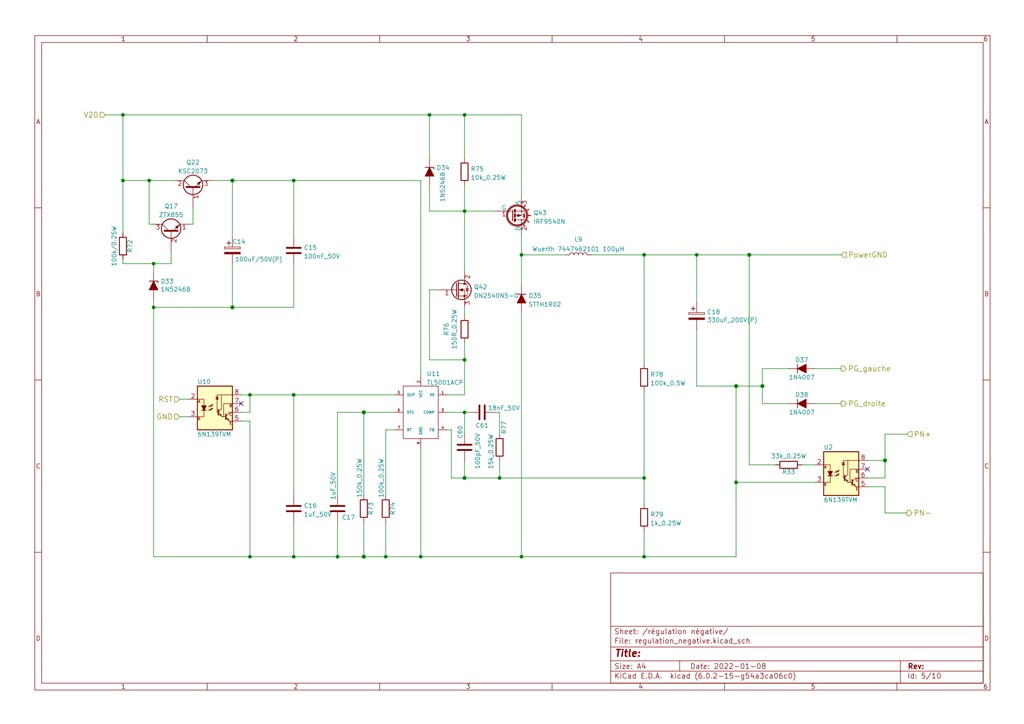
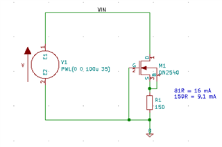
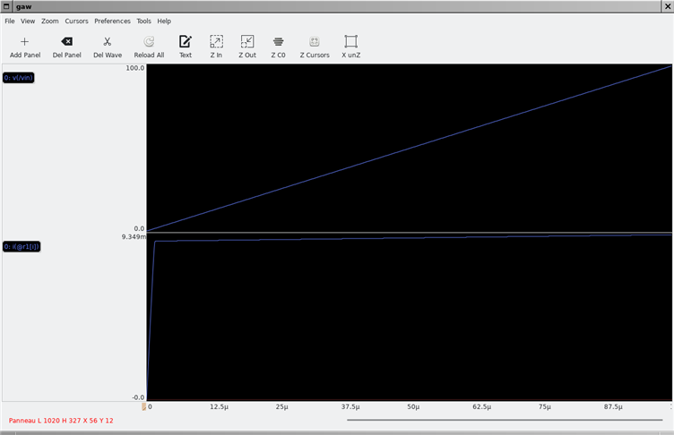
V20 is a 28Vdc input. Q22 creates a 14V between TL5001A's Vcc and GND. D34 is uses to limit Q43 Vgs. Q42/R76 limits Vo current @ 9 mA. Max output current is less than 50 mA and I expect -100V between PowerGND and PG_gauche/PG_droite.

Before creating a PCB with this circuit, I would know if it will run as expected.

Best regards,

JB

  • Hi JB,

    Thank you for posting and for considering our solution.  I think the driver logic inverting FET Q42 should be used with its source pin to IC GND node (which is also your -100V rail in the configuration), and R76 be inserted between the drain of Q42 and the gate o Q43.  Do you agree?

    Thanks,

    Youhao 

  • Hello Youhao. I don't understand issue you see with Q42. Q42/R76 limits current at 9 mA. Thus, voltage at Q43's gate is always between V20 node (28Vdc) when TL5001 internal switch is open and V20-Vz(D34) = 28 - 15 = 13V.

    Example:

    M1 acts as a current limiter. For simulation, V1 takes values between 0 and 100V (and not 35V, I haven't modified schematic).

    Best regards,

    JB

  • Hi JB,

    Very sorry my bad:  I thought M1 was a regular NFET just by seeing the symbol.  I should have done this yesterday:  I just checked the datasheet online and realized M1 is a depletion mode FET, which we do not use often in our regular work. 

    Then, your circuit should work.  I just recommend to things:

    • reserve an RC snubber across D35 in case it is needed after testing, then you can avoid doing a new PCB.
    • Add a RC branch in parallel with R78 (like seen in the datasheet example circuit, which I copy and pasted below).  This is a voltage mode controller and it need this RC to help stabilize the loop with a Type-3 compensation.

    Again, sorry for the confusion and good luck in your project.

    Thanks,

    Youhao

  • Thanks a lot, I will test this circuit.

    Best regards,

    JB

  • Bad news, Youhao.

    I have wired a test and TL5001 doesn't start.

    Green is GND, white is +15V and I expect between black and green around -100V.

    I have simplified my test and I have removed D3, R9, Q3 and Q4. Now, I have put a 15V power supply between green and white and another floating power supply (15V also) between pin 2 of TL5001 and black. Same result.

    I'm trying to simulate this circuit in PSpice (trial version) as PSpice has a TL5001 model as you doesn't provide model for this chip, but if you have an idea...

    Best regards,

    JB

  • Hi JB,

    Sorry to hear.  It seems a problem in the gate drive circuit.  The 10k (R3) does not allow the PFET's inherent gate capacitor to be discharged in time.  I remember you have an earlier circuit that can turn-off the PFET quickly.   I checked the PFET's datasheet it has >1nF inherent gate capacitance. 

    Before you do anything else, would you check if the TL5001 output is switching? 

    Thanks,

    Youhao

  • Hi Youhao,

    I will check asap and will try to reduce R3.

    Thanks a lot,

    JB

  • Hi Youhao,

    I have reduced R3 until 1,8kR without difference. TL5001A doesn't start and SCP is around 2,5V. Thus controller triggers a short circuit condition.

    Best regards,

    JB

  • Definitively, TL5001A doesn't run as expected in this configuration. I have replaced this component by a MC34063A that perfectly runs as expected but it's power supply configuration is slighly different and if it can produce a negative output from a positive power supply, it only accept 40V between positive and output voltages.

    Thus I have used this MC34063A in boost configuration (with an external switch and a snubber) and a charge pump.

    Regards,

    JB