This thread has been locked.

If you have a related question, please click the "Ask a related question" button in the top right corner. The newly created question will be automatically linked to this question.

LM25184-Q1: LM25184-Q1

Part Number: LM25184-Q1
Other Parts Discussed in Thread: LM25184

Hi teams:

I have some issue about LM25184 start up waveform. The sencondary windings of design are two windings, and each winding is 12V/0.1A.

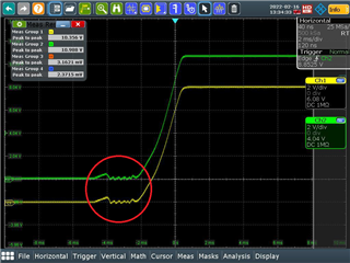
The left waveform that use CR mode (for each winding load is 120 ohm) test start up characteristic.

The right waveform that use CC mode (for each winding load current is 0.1A) test start up characteristic.

The CC mode waveform is different from CR mode at red circle . Why?

Thanks.

Best Regards

Nick

  • Hello

    All electronic loads have internal feedback loops to set the current both in CC and CR mode.

    These loops can interact with the control loops of any DC/DC converter.

    As an example, some electronic loads can pull the output voltage of the regulator negative before it

    starts up.  This may cause the regulator to fail to start up at all.  I would expect to see differences in the 

    start-up behavior of a DC/DC converter depending on whether the electronic load is set to CC or CR, or the

    type of electronic load that is used.  We use an actual resistance load when testing start-up of our converters

    to prevent these kinds of anomalous behaviors.  

    The best way to get consistent results is to use an actual resistance as the load during start-up.

    Of course you must test with your actual load in order to determine if the regulator is suitable for your particular

    application.

    Thanks

  • Now, I see.  Thanks a lot.