


Hello,
I want to charge a one-cell battery up to some certain level of voltage, like 3.9V. To choose just one threshold, most likely, makes the circuit unstable and causes many other issues for the rest of the components as well. Therefore, I decided to make an error margin by using Schmitt Trigger.
My goal is to charge the battery until it reaches 3.9V (arbitrarily) and once it hits that voltage, I want the transistor to stop conducting. For the other threshold, like 3.0V, until the voltage of the battery drops that level, I don't want to charge the battery.
In order to charge the battery, I need low voltage as an output to trigger the base pin of PMOS. Here is what I tried,
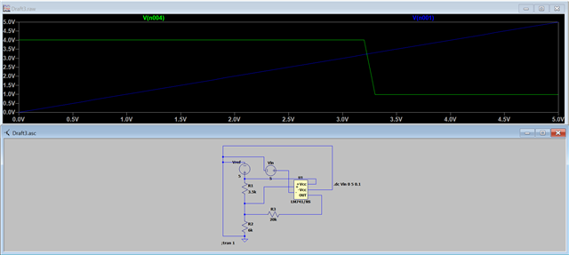
I made a DC Sweep simulation on LTspice. V(n001) - the blue colour- represents the voltage of the Vin which corresponds to the voltage of the battery. It is being charged (since it's voltage rises) and goes from 0V to 5V. (Actually, it should not reach the 5V because it is a li-ion battery without something different.) When the voltage of the battery hits around 3.3V (resistors are randomly valued), the output voltage -green colour- drops down. However, what I want to do is the opposite of this outcome.
While the battery is being charged, or actually to charge the battery as a requirement, the output voltage has to be low. Therefore, while Vin (Vbat) is rising from 0 (not real) to 3.3V (from the simulation result), the output voltage is low that I don't want. Instead, I want it to be low during charging state because this is requisite. Therefore, whenever it reaches 3 point something (from 0 to that level), I want the output voltage to be high so that there will be no conducting anymore.
To sum up, I have the opposite result of my goal. I need your help, please help me solve it. It may not be so hard to do or maybe it is but I couldn't. I thought inverter and other stuff but still I couldn't reach a satisfying result.
Note, Vcc is supplied by the Vref and the symbol of the opamp is wrong. I just downloaded the "spice" of the component (LM741/NS) and I didn't arrange the symbol. Also, I don't want to control this charging and termination operation by the charger IC itself or by something different. I need to solve this issue in this way.
I will be so much delightful if you could help me. Thank you for taking your precious time.
Best Regards,
Caner
