This thread has been locked.

If you have a related question, please click the "Ask a related question" button in the top right corner. The newly created question will be automatically linked to this question.

TPS6594-Q1: power consumption

Part Number: TPS6594-Q1

Dear team,

Recently my customer is testing the power consumption under different states. We have one question below,

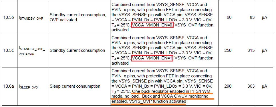
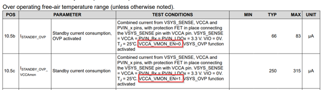
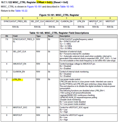
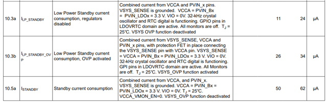
1. What is the difference between Standby and LP Standby? LP Standby mode consume less current compared with standby mode, so which part is disabled in LP standby mode while enabled in standby mode?

Thanks & Best Regards,

Sherry

  • In LP_STANDBY mode, the internal LDO is disabled. This is represented by VOUT_LDOINT pin.

  • Hi Michael,

    Is this parameter 20us or 4us related to quiescent current?

    Thanks & Best Regards,

    Sherry

  • Hi Sherry,

    Michael is currently out of office, please allow for a delay in response until Tuesday.

    Best regards,

    Layne J

  • HI Sherry, 

    This register setting changes the voltage monitor deglitch filter time. Could you elaborate what you mean is is related to quiescent current?

    Thanks.

    Regards,

    Tomi Koskela

  • Hi Tomi,

    My customer is testing our PMIC's standby current. Currently the test result is larger than 300uA which should be in 10.5c status. My customer wants to decrease the current to the level of 10.5b, so they set VCCA_VMON_EN=0, but the current is still around 300uA which seems no change.

    If we want to achieve the current of 10.5b, Do other registers need to be set? Their current register setting is as below.

    Pmic_I2C_Write(0x86, 0x03);

        /* Clear INT_STARTUP */

        Pmic_I2C_Write(0x65, 0x02);

        /* Configure GPIO4_CONF */

        //allen modify 0xc0 -> 0xcc

        Pmic_I2C_Write(0x34, 0xcc);

        /* Configure INT_GPIO1_8 (enable GPIO4 interrupt) */

        Pmic_I2C_Write(0x64, 0x08);

        /* Configure MASK_GPIO1_8_FALL (configure GPIO4 falling edge interrupt) */

        Pmic_I2C_Write(0x4F, 0xF7);

        /* Change FSM_I2C_TRIGGERS */

        Pmic_I2C_Write(0x85, 0x40);

         /* Change FSM_NSLEEP_TRIGGERS */

        Pmic_I2C_Write(0x86, 0x00);

    Thanks & Best Regards,

    Sherry

  • Hello Sherry,

    Can they confirm they've isolated the voltage and current sources? Is VIO indeed 0V? Does their design have a FET between VSYS and VCCA and if so, are they measuring after the FET?

    If testing on the EVM, it can be difficult to isolate current going into VCCA and VIO pins.

  • Hi Michael,

    1. Could you please tell me how to isolate the voltage and current sources?

    Can they confirm they've isolated the voltage and current sources?

    2. Yes, VIO=0V

    Is VIO indeed 0V?

    3. They should test the current before FET. The specs in the datasheet is measured after the FET?

    Does their design have a FET between VSYS and VCCA and if so, are they measuring after the FET?

    Thanks & Best Regards,

    Sherry

  • Hello Sherry,

    The "Test Conditions" column explicitly states those numbers are the sum of the current heading into VCAA, VSYS_SENSE,  and PVIN_x pins. Therefore, they are measured after the FET.

    Without seeing the schematic, I would say using small value sense resistors on the input power lines would allow them to measure the input at each pin.

  • Hi Michael,

    Thanks for your reply!

    I understand your point. But I still have some confusion for below table. Comparing 10.5b and 10.5c test condition, the only difference  is the setting of VCCA_VMON_EN, so I think VCCA monitor function will consume 250-66=184uA current, which should be independent of the measured point.

    In customer's test condition, when they change VCCA_VMON_EN bit from 1 to 0, the current hardly changes. My customer is computing the total solution sleep current consumption, so they have to test the current at 6594's input VSYS, the smaller the better. How do we operate to reduce the current below 100uA?

    Thanks & Best Regards,

    Sherry

  • Has the customer tried setting LPM_EN =1 to reduce the current further?

  • Hi Michael,

    Thanks for your reply! But the current still hardly changes after setting LPM_EN =1. Now we want to reduce the current below 100uA. Do you have the configuration list? I can try it in our demo board.

    Thanks & Best Regards,

    Sherry

  • I am conferring with the test team on their set up and will get back to you soon.

  • Hi Michael,

    Thanks for your reply!

    1. Please help discuss with test team for the 10.5b configuration;

    2. The register configuration that I listed above is trying to transfer ACTIVE mode to S2R mode. In this mode, what is the current consumption?

    3. For 10.5b, it is for standby mode. In order to transfer ACTIVE mode to standby mode, we need to pull ENABLE pin to low signal instead of above register configuration, right?

    Thanks & Best Regards,

    Sherry

  • Hello Sherry,

    Mike should be able to respond to you by tomorrow.

    Regards,

    Alex

  • Hello Sherry,

    I was able to achieve 38uA on the TPS65941515 with the following steps:

    1. Raise VSYS to 3.3V
    2. Set ENABLE pin High
    3. Write 0x03 to register 0x86
    4. Clear interrupts
    5. Write 0xC0 to register 0x7D. This masks the impact of NSLEEP1 and NSLEEP2 bits on FSM state transitions
    6. Write 0x01 to register 0x85. Setting TRIGGER_I2C_0 =1 sends device to standby mode no matter it's current state.

    Important note: On the TPS65941515, Low Power Standby is the default standby mode for this NVM. Also, for this device the VCCA_VMON is disabled when entering low power mode. This would explain why you did not observe a difference when setting VCCA_VMON=0 or 1 as it is already turned off in your device.