This thread has been locked.

If you have a related question, please click the "Ask a related question" button in the top right corner. The newly created question will be automatically linked to this question.

UCD3138: Support setting up CBC

Part Number: UCD3138

Experts,

I am struggling to follow along through the programmers manual get all the correct steps to setup CBC routed from an ADC input to DPWM0. Can someone provide a checklist of command I need.

My assumptions of order are,
1.Setup Acomp
2.Setup Faultmux
3.turn on CBC enable
4.Anything need at the DPWM module, blanking?. I currently am only using DPWM0 in normal for a buck topology.

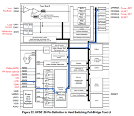
The picture below is how I am trying to setup my prototype.

Any explanation or assistance will be appreciated. CBC seems to be split all throughout the programing manual so it is hard to track form start to finish.

  • I'll try to give you a complete list of the bitfields you need to set up, but no guarantees.  On the UCD, it is likely that you will sometimes have to search for the missing bitfield.  

    FaultMuxRegs.ACOMPCTRL0.bit.ACOMP_EN = 1; //Global enable of ACOMP function
    FaultMuxRegs.ACOMPCTRL1.bit.ACOMP_D_THRESH = CBC_THRESH; //set to threshold voltage for current sense CBC point
    FaultMuxRegs.ACOMPCTRL1.bit.ACOMP_D_POL = 1; //set to trigger when voltage goes above threshold - this is the default
    FaultMuxRegs.ACOMPCTRL1.bit.ACOMP_D_SEL = 0; //set to use D thresnold for D comparator - also the default

    FaultMuxRegs.DPWM0CLIM.bit.ACOMP_D_EN = 1; //enables comparator D to limit current on DPWM0
    FaultMuxRegs.DPWM1CLIM.bit.ACOMP_D_EN = 1; //enables comparator D to limit current on DPWM1

    Dpwm0Regs.DPWMCTRL0.bit.CBC_PWM_AB_EN = 1; //enables CBC to afect DPWMA and B
    Dpwm0Regs.DPWMCTRL0.bit.CBC_ADV_CNT_EN = 1; //also required to enable CBC

    Dpwm1Regs.DPWMCTRL0.bit.CBC_PWM_AB_EN = 1; //enables CBC to afect DPWMA and B
    Dpwm1Regs.DPWMCTRL0.bit.CBC_ADV_CNT_EN = 1; //also required to enable CBC

    I put in both DPWM 0 and 1, but you can take 1 out if you want to.  But I assume that if you have a CBC you want to shut everything off.  

  • Thanks Ian,

    This should save me a ton of time. My intent is to abort the PWM cycle but not shutdown (should put it in kind of a constant current mode). I want to sense this event and send that to my other system controller to handle sequencing. Planning to try this today.

    Thanks,

    Dennis

  • Dennis, you will have to use the ACOMP_D bits in the fault status and interrupt registers to see if CBC has been active.  The DPWM has no bits to indicate that CBC is active.  There are FLT_CBC bits, but those are used when you are using the CBC as a fault, which means it will shut down the DPWMs after a specified number of consecutive CBC occurrences.  That's a different thing with a different setup.  

    I would suggest that you just poll the ACOMP_D bit in the fault status register and don't use the interrupt.  If you do use the interrupt, disable it as soon as you get an ACOMP_D interrupt.  If it stays at overcurrent, it will keep interrupting every switching cycle, which will probably lock you up in the interrupt.  

    Note that if the load is at CBC the voltage will probably drop.  This will cause the integrator in the PID to ramp up trying to get the voltage back up.  The CBC effectively disconnects the feedback path of the filter.  If the current does a step drop, you will may exceed your Vout limits before the PID can adjust.