This thread has been locked.

If you have a related question, please click the "Ask a related question" button in the top right corner. The newly created question will be automatically linked to this question.

TPS61160: Protection from ESD

Part Number: TPS61160
Other Parts Discussed in Thread: TPS61161, TPS92360, , TPS61165

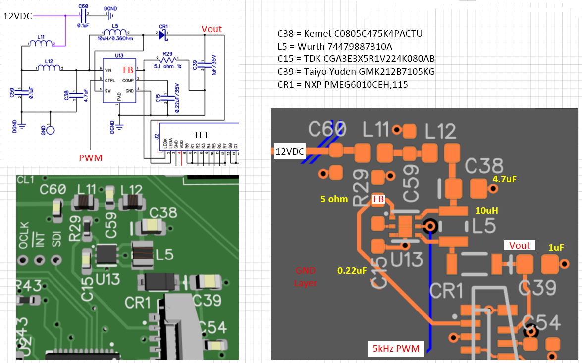
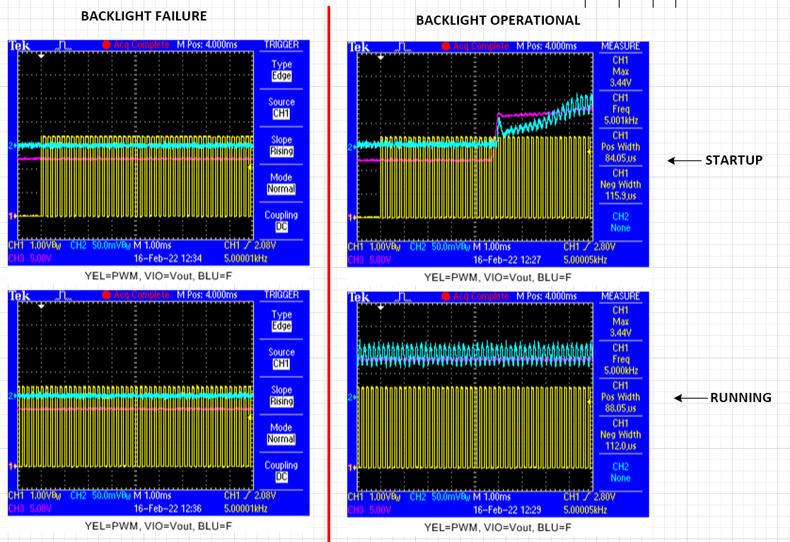
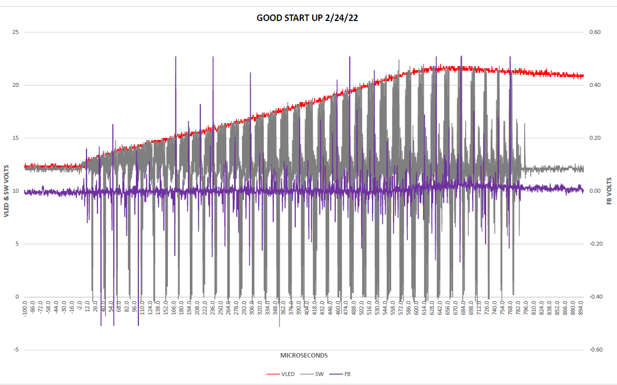
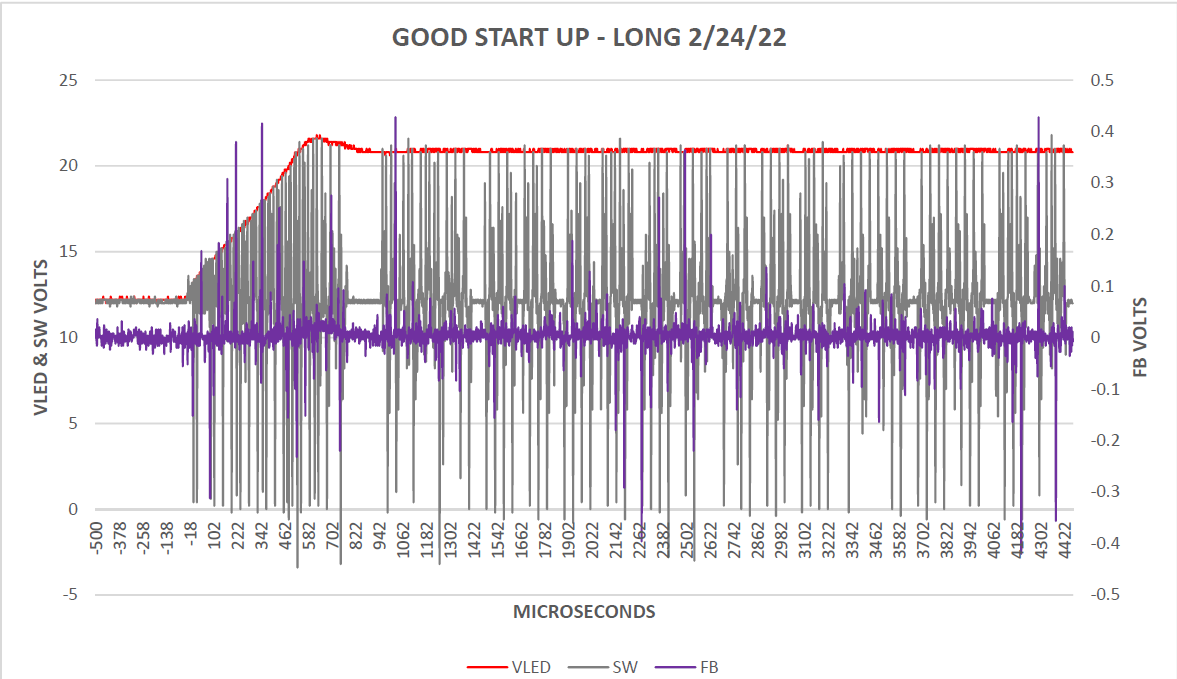
We are using this chip to drive the LED backlight for a TFT display. Initial prototypes worked extremely well, but we have just finished a 40 piece production run where we had 6 failures of this chip. Our next run is 150 units for long term field tests so we need to get this straightened out. I do not believe at all that we had defective parts, based on my test data it looks like we had ESD damage to the FB pin. This seems to have occured either during handling of the boards after reflow or during connection of the LCD display to the connector which is right next to the TPS61160.

What I would like to do is insert a resistor between the cathode of the LED backlight and the FB pin (10 ohms?) and put a transient supressor across the 5 ohm FB resistor to ground. I see that the Vmax on this pin is 3V (same as the COMP pin) I dont think that this will cause any operational issues except for the extra 400mV which will be generated across the 10 ohm resistor. I may also consider an ESD supressor across the COMP capacitor. These are simply right where an operator would place their fingers, we are all ESD gounded but I have no other explanation. 

Does anyone see any issues with this, or have experienced anything similiar?

Thanks for any feedback!

Larry Affelt

  • hi Larry

       Can you help clarify how you get the ESD conclusion based on data? Are there any abnormal waveforms available?

  • The ESD is honestly conjecture at this point, the failed units simply do not appear to operate at all, no wave forms to show. I personally tested a small batch of brand new units late last night under very strict ESD control and found the same failures. All the power and signals (45% 5kHz 3.3V square wave) are present at the proper pins and the device simply does not start switching or turning on the FB reference voltage.

    What I am looking at right now is the inductor, this design is currently using a multilayer inductor from Wurth. After reviewing the TPS spec (for the nth time) I looked at the suggested inductors and they are all wirewound. I now have two different Murata wirewound inductors to try, one with a ferrite core and the other with a iron powder core. 

  •  Here is an image of the design, dont see where I have gone wrong

  • I have tried two of the ferrite core inductors in place of L5 with no change, output voltage to the backlight is still the 12V DC input, no switching detected.

    The LC filter components (L11,L12,C59,C60) are there to prevent the 600kHz switching noise from reflecting back onto the 12V system power. This design has to meet EMC requirements and the 12V exits the board thru multiple high-side automotive drivers. Thinking that the two inductors might be interfering with the operation I removed them and shorted the pads out ... still no luck

  • Hi Larry

        1. Can you help set the oscilloscope to capture the start-up waveform to ensure the device does not trigger any fault as the period of time may be very short?

        2. For the schematic, I would like to know the LED configuration inside the TFT display, LED string voltage, current, etc.

        3. Actually from the layout, FB trace from connector to FB pin is quite long that is not beneficial to noise immunity. Besides, I also see the 5kHz PWM trace goes cross FB trace and SW although they are not in the same layer, is there ground layer between top layer and bottom layer? 

        4. Due to concern in #3, can you provide waveforms of FB, SW, VLED, ILED for those boards that can power up normally? better to have both start up result and stable result.(also some zoom in detail)

  • Hi Mason,

    I'll address #3 first, this is a 4 layer board so there is a ground plane and 3.3V power plane between the FB and SW traces.

    I will get you the scope traces you mentioned on both good units and non-starting units today. I have considered that the 26V open circuit protection was being triggered but I havent been able to detect that. Here is a comparison between the two scenarios and I have tried to trigger on the upslope of the FB signal but havent seen anything, I will try again on the VLED or SW lines. How fast is the response time of the open circuit detection? I don't see anything in the spec on that 


    Thanks for helping me with this!

  • The LED string says it needs 40mA at 25V, I am seeing about 22-23V on operating units like in the above trace. And yes, that is way too close to the 26V open circuit threshold but I have not seen evidence of that although it makes a lot of sense! My plan is to move to the TPS61161 in volume production.
    The scope traces above are typical I can see that the start up signals on the VLED and FB are in the 100's of uSec range which I should have been able to trigger on. But I have not tried triggering on the SW signal, I'll know more later

  • Hi Mason - I have inserted two pictures of a good start up of the TPS61160. I was triggering on the down slope of the SW line and that triggered very reliably. When I switch over to a 'bad' board under the same triggering setup the scope does not trigger. I tried several times, moving the trigger voltage closer to the 12V nominal value on the SW line but no luch. The chip doesnt try to start up and trip on the 26V open circuit level ... the SW output never switches. Very strange

  • We have taken microscope pictures of two different production runs, the first run of these in September '21 was made with chips purchased from DigiKey, these boards that we are dealing with now have IC's from an overseas source "Win Source Electronics" due to availability. The molding looks slightly different but the font for the text on top is much much different! Could we have gotten counterfeit chips?

    DigiKey:

    Win Source:

  • hi Larry

        Actually, we can only ensure the normal operation of the devices purchased from TI or its agent.

        From your test result, device does not trigger any fault. It is likely to get counterfeit chips or they may not be properly stored.

  • Hi Mason,

    I totally understand, and I don't think storage was an issue. These parts came from overseas with minimal labelling or marking, so my issue now is to find valid replacement parts. My production is scheduled to ramp up to >3k per year later this year, this is a 150 piece run for field trials. We use 4-5 other TI parts on this assembly (buck converters, current limiters, etc) but this part is the only supply issue.

    Thanks for all your help

  • hi Larry

        Fully understand your concern. For the replacement, I would like to confirm your operation condition:

    Vin 12VDC, VLED 25VDC, ILED 25mA, only one string

       Basically, I think TPS6116X, TPS92360 can satisfy the requirement mentioned above.  

  • Correct except for the current, its one string @40mA

  • Hi Mason,

    1 question which I cannot find a description of: What is the difference between the TPS61160 and the TPS61160A parts?

  • hi Larry

        The only difference is that TPS61160 has one-wire function while TPS61160A does not have. The detailed description of one-wire function can refer to data sheet.

         For your requirement, TPS61160, TPS61161, TPS61165 can be the candidates.

  • Hi Mason,

    I see I did not look deep enough into the specs, since I am using the standard PWM mode we can use either.

    Thanks