Other Parts Discussed in Thread: BQSTUDIO
I've got a design that is quite similar to the BQ76952 evaluation board.
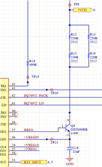
We use the REG0 (NPN) pre-regulator and we configure REG1 for 3.3V. REG2 is unused. REG1 is actually only used to enable a switch mode power supply.
Using bqStudio, I import the default settings, then set the bit to enable REG0, and set the bits to enable REG1 for 3.3V. I can see REG1 turn on, 3.3V as expected. REGIN is ~5.5V as expected.
However, I'm seeing about ~22mA flowing into REGIN (measured at the resistor that is in series with the NPN). At first I thought it was REG1 getting loaded down by something, so as a test I disabled REG1 and enabled REG2 instead (to make sure REG0 is enabled).
With REG1 disabled and REG2 enabled, I see REGIN=5.5V, REG1=0.0V, REG2=1.8V (which is what I set it to), but I still have that ~22mA flowing into REGIN. Since REG2 isn't connected to anything else, that current has to be going somewhere in the chip.
The voltage at BAT is higher than REGIN, so it's not that diode that the datasheet makes reference to.
Can you think of any reason there would be ~22mA flowing into REGIN?
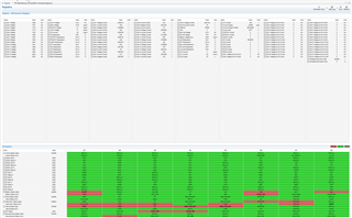
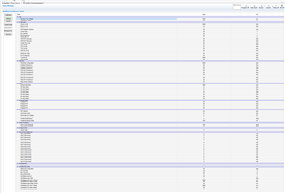
Here are screenshots of the registers and data memory, in case that's any help: