This thread has been locked.

If you have a related question, please click the "Ask a related question" button in the top right corner. The newly created question will be automatically linked to this question.

TPS62902: Immediate high side short upon power up

Part Number: TPS62902

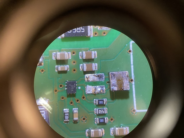
Update: it turned out to be an assembly error (the inductor was rotated 90 degree)

I utilized Webench to design a simple DC/DC circuit with these parameters:

Uin: 3V0 to 7V5

Uout: 2V8 (200mA)

We designed the actual circuit and fabricated the prototypes.

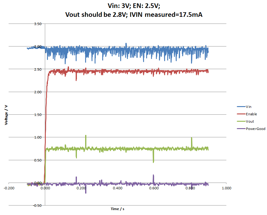
During the test we encountered a catastrophic failure on two samples: as soon as the input voltage rises above 3 or 4 Volts the VIN shorts permanently with the SW pin (I confirmed this short by measuring these pins after de-soldering the IC). Because our supply of regulators is extremely limited and the next shipment is expected next year we halted all tests until this issue is resolved. This short happened with a current limit set of 5mA in out lab bench supply.

Are there any suggestions as to why the the simple smoke test fails so spectacular? I will attach an image from the actual schematic:

Components:

IC300: TPS62902RPJR

Inductor L300: Würth 74438336010

Maybe you can help to clarify what went wrong

  • Hi Marius,

    The schematic looks good to me. What is your load current during the start up? 200mA? 0A? Did all the boards damage with Vin short to SW? Or just 2? Do you have a waveform for Vin and SW during start up? Did you see the input voltage drop during start up since 3V is just about Vin UVLO. The input supply current limit 5mA is too small at 2.8V/200mA. Please change to 1A current limit and test it again. Please send us the PCB layout if it is possible.

    Thanks,

    Nancy

  • Hello Nancy,

    1) There should have been no load on startup because I removed a 0-Ohm resistor to the right of the two Zener diodes N300 and N301 prior to testing. Therefore the output of the regulator was unloaded.

    2) There was no short circuit between VIN and SW before the test. I can be sure about it because when I applied 2V in the beginning there ware basically no current flow and the output of the regulator was 0V (this is the expected behavior). Once I crossed about 3V the short circuit appeared. The output voltage was equal to the input voltage, above 4.3V the zener diodes got active and clamped the output voltage (and my lab power supply's current limit kicked in). 

    3) As the 1st board failed I thought it might have been an ESD problem or an other unknown error. But as also the second board failed in the same manner I stopped the test. I only have 20 boards and we can't afford to destroy more than 4 of them. So in total I only tested two boards and both failed the same way.

    I de-soldered one of the broken regulators and measured about 0.3 Ohms across VIN and SW.

    4) I can wire up the third board with my oscilloscope and power it up to capture how it is destroyed. Maybe this will help to identify the problem. I will reach out when it is done

    5) I attach an image of the Layout. It shows the Layer L1. Layer L2 and L3 are filled with GND and on L4 are just some test points (connected with the vias seen on L1):

    Kind Regards,

    Marius

  • I performed the measurement with a third prototype and managed to not destroy the regulator by keeping the input voltage at 3V. The regulator draws about 17.5 mA. I only switch it on for one second to avoid permanent damage. The output voltage is around 0.75 V which look suspiciously like a diode voltage. However I de-soldered all external diodes of this circuit (including the Zener diodes) without luck:

    The reason for the noise is a sub-par GND connection to the oscilloscope, It should have no significant impact.

  • Hi Marius!

    Our team will reply you soon!

    BSR-MV

    Shuai

  • Hi Marius,

    I do not see an obvious issue with the design. I would check the input supply behavior when current limit is hit. During startup, the converter current demand will be much higher and how the supply reacts to the current limiting may cause a problem. 

    To save another IC, you can test just the input supply leads across a fixed resistor (maybe 100 Ohm) and to measure the supply and current as you increase Vin. There might be some voltage spike when it hits current limit. Alternatively, you can have try holding EN low while you ramp up VIN. Then, take EN high (after the caps are charged and UVLO is exceeded). You can also try replacing the supply which has higher current limit to see if that starts up the design.

    Thanks,

    Amod

  • Thank you every one for your support and suggestions. I finally found the error after dissembling the entire circuit piece by piece:

    It was just an assembly error: the Inductor was rotated by 90 degree on all boards

    Because of its DC resistance of 0.03 Ohm this was difficult to spot.

    Sorry for taking up your time with such an obvious error. We have to have a serious talk to our EMS Partner.

    Kind regards, Marius