This thread has been locked.

If you have a related question, please click the "Ask a related question" button in the top right corner. The newly created question will be automatically linked to this question.

TPS40305: Getting the peak of 35MHz

Part Number: TPS40305

Hello Team,

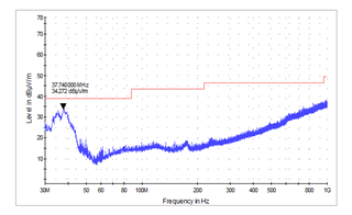
We are getting the 35MHz peak during the FCC-15B RE testing.

Here is the original thread link.

We have bypassed the input LC filter and looks like an improvement but that is not a major one that we can test in the lab.

Let us know a further workaround.

Regards,

Pratik Panchal

  • Hi Pratik,

    Our US team will check it and reply you soon.

  • Hi Pratik,

    Can you please provide the PCB layout of all layers and the bill of materials? Also, can you show me the new EMI result that shows the 35MHz peak? Thank you.

  • Hello

    Tomoya: Can you please provide the PCB layout of all layers and the bill of materials?

    Pratik: Here is the snapshot of all layers & BOM file.

    TPS40305-BOM.xlsx

    TPS40305-ALL-Layers.pdf

    Tomoya: Also, can you show me the new EMI result that shows the 35MHz peak?

    Pratik: Here is the snapshot of the failure peak with only TPS40305 is ON, all other things are OFF condition.

    Let me know if you have any queries.

  • Hi Pratik,

    It looks like your snapshot shows a passing result, but I'm assuming it fails after all other things are turned ON?

    The first thing I would recommend is to add an HF capacitor near the input connector right before the input cable. 33nF, 0805 size capacitor might be a good option because it seems to have the lowest impedance around 35MHz.

    Is the white border a provision for a metal shield? If not, it is very effective at improving RE, so I recommend it if that's an option.

    The RE at >30MHz can be tricky to fix (usually common-mode noise related), and you can improve it by adding more GND plane areas and via stitching them together for low-impedance GND and better shielding. I recommend flooding with GND in the unused space (e.g., layer 8, etc.).

    Another option is to use a common mode choke, which in my experience has been very effective a reducing both CE and RE. You can replace the LC filter with a common mode choke.

  • Hello

    Thanks for the response.

    Can you give the value of CMRR which we need to try?

    Regards,

    Pratik Panchal

  • Hi Pratik,

    For the common mode choke, look for one that has the highest common mode impedance around 35MHz, as shown below. Look for the impedance vs. frequency graph in the datasheet. Also, remember to look for other specs such as the current rating can support the input current, etc.