


I recently purchased the TPS40200-Q1 and I am attempting to design a DC/DC converter based on the SwitcherPro Design with the following specifications:
Vin(min) = 7.4V
Vin(max) = 12.4V
Vout = 6.25V
Iout = 3A
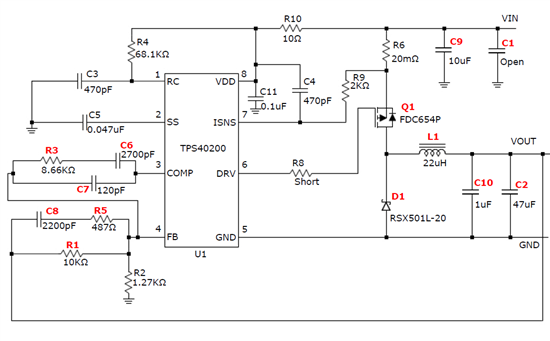
The problem is the circuit does not provide the required current. It appears almost any significant current that passes through results in the device moving into overcurrent shutdown. As seen on SS (pin 2). The output voltage will set to the proper value, but as soon as a load is placed across Vout, overcurrent kicks in. To test the amount of possiblecurrent I places different resistors across the output. I've tried several of the techniques listed in other discussion boards:
I've moved R10 to the proper location and selected the values of R10 and C11 so that they match the time constant of the C4 and R9 filter.
I attempted shorting C4 and R9 to eliminate the chips over currrent response.
I've attempted several different feedback and comparator values, including the ones provided by the SwitcherPro Design.
It appears the over current shutdown occurs regardless of the rest of the system. Could this be the result of a bad chip? Or am I missing something in the design of the buck chopper. Any advice/suggestions would be greatly appreciated.
Thank you,
Joe Senerchia
