This thread has been locked.

If you have a related question, please click the "Ask a related question" button in the top right corner. The newly created question will be automatically linked to this question.

BQ24040: PMIC Charging Issue - Battery Detect Mode

Part Number: BQ24040

Hello,

I am using BQ24040 for charging a 300mAH LiPo battery for a number of years. We have been getting customer returns on battery charging issues.

On closer inspection of returns, we have noticed that the PMIC is going into battery detect mode and staying in that mode.

We have done a lot of investigation and have observed on the returned units, the resistance path of the positive or negative battery terminals can be 0.2- 0.6 Ohms higher than a non-customer returned unit.

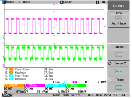
This led us to placing a 0.5Ohm resistor in the positive or negative battery terminal paths to the PMIC.  Every time we observed, the unit going into battery detect mode and the charging current varying from 0-XmA every 25ms. See plot below.

Would you expect if the resistance is  >0.1Ohms on the positive or negative battery terminal path to the PMIC that the PMIC would enter Battery detect mode? 

Is there any way to avoid going into battery detect mode for this PMIC or to overcome this issue that we are seeing.

Thanks Aileen


PMIC out [pink signal] it varies between 3.8V and 4.2V every 25mS

Charge Indicator [Blue Signal) high impedance

Power Good [Orange Signal] Low, power is good

Charging Current [Green Signal], it is varying every 25 mS


  • Hi Aileen,

    I do not think that the >0.10 ohm resistance would cause battery detect mode.

    I also have few questions:

    1. When the resistance was measured, was the charger VIN disconnected?

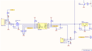
    2. Would you be able to send over a schematic so we can get more info on what may be causing this behavior in the returned units?

    3. Have you tried to place a large capacitor ~400uF on the bat pin?

    Let me know and keep me updated if #3 resolves the issue. Thanks,

    Jackson

  • Hi Jackson,

    Thanks for your reply. Here are the answers to your questions

    1. Yes, when the resistance was measured, the charging Vin was disconnected. 

    2. Here is the schematic

    3. I haven't placed a 400uF cap on the bat pin. Is this recommended in the Datasheet?. I will be in the office next week, so I will try this.

    Thanks and Regards

    Aileen

  • Hi Aileen,

    I will take a look at this more tomorrow in the lab. Could you try a 2.2uF cap as well?

    Ill let you know tomorrow of what I am able to find.

    Thanks,

    Jackson

  • Aileen,

    I have not been able to replicate the issue that you have been seeing on your returned units even after placing a 0.5Ohm resistor as you did. Have you tried adding the 2.2uF cap? Please let me know what you find or let me know of any further questions you may have regarding the behavior you are seeing.

    Thanks,

    Jackson

  • Hi Jackson,

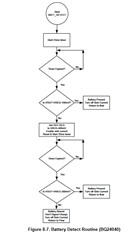
    I have placed a 2.2uF cap and it doesn't fix it. I have seen that sometimes for the issue to be seen, I need to place a 0.5Ohm resistor on both the  battery positive path and the TS paths at the same time. In the battery detect flow diagram below, if the battery isn't present, does the PMIC OUT pin go to 4.2V and it fails the decision 'is vout < vreg - 100mV' and continues then into the next part of battery detect mode.

    But in order for it to start any battery detect mode, Vout needs to be > 4.1Vs?

    Is this correct?

    Thanks Aileen

  • Aileen, 

    Battery detect mode can be entered from removing the thermistor, pulling the TS terminal up to TTDM threshold, or by removing the battery. I believe the issue here is that the increased resistance on both BAT+ and TS is causing the IC to enter TTDM and thus starting battery detect mode. One way to avoid this issue would be to add a 237k resistor between Ts and VSS to disable this functionality all together.

    Thanks,

    Jackson