This thread has been locked.

If you have a related question, please click the "Ask a related question" button in the top right corner. The newly created question will be automatically linked to this question.

TL494: abnormal frequency issue

Part Number: TL494

Hi team,

My customer find there is an issue in flyback charge application need your support.

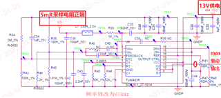
Application scenario: Charging cabinet output voltage is 55.6V and the battery pack is 42.6V, they use TL494 on protection board for limiting current

Test condition: Connect battery pack to the charging pert, the battery pack will enter overcurrent protect and after 1s, enable protection board to charge, but there will lead to a 100+ A current when enable this protection board work, result in fuse blowing.

Analysis: we find that there are some abnormal behaviors in output and working frequency. The part of schematic and waveforms are as follow. The green line is current, blue is MOS driver signal, yellow is VCC and red is V_REF.

Could you help to find the reason for a very high frequency leading to 100+A current? 

Any question pls contact me, thanks!

  • Darren,

    I assume this is a CC/CV converter? Parts of the converter that should be measured and analyzed are the current sense signal, CC/CV amplifier voltage ref and feedback.

    Regards,

    Steve

  • Hi Steve,

    Thanks for your reply. Since the CC/CV amplifier feedback signal is small and sensitive with noise, it is hard to measure and analyze. 

    Do you have any suggestion for capturing the feedback signal? 

    This issue happen at the beginning of power-on, do you think change the soft start can help to find the root cause?  Waiting for your reply!

  • Darren,

    From the waveforms, it appears like CV initially, then we see a huge current increase but the converter does not appear to be switching over to CC and regulating/limiting the charging current. Instead of plugging the charger into a battery pack I believe you need to recommend to back up and debug using a controlled CC/CV E-Load. Study the CC an CV error amp signals. Is the mode change happening quickly, without delay in both directions, CC to CV and CV to CC? Check the VREF, CS, Bias to the CC/CV amps. Monitor these signals as you introduce CC and CV loads in a controlled manner. Be sure to current limit the input supply to prevent damage to the charger. the input signals to the CC/CV amps are high impedance and you should be able to measure these with standard oscilloscope voltage probes. The CC/CV amp outputs are low impedance but they should be diode Or'd together and you should be able to measure the Or'd result after the Or'ing diodes. You show 100+A current but you did not mention the CC regulation target? 

    Regards,

    Steve M