This thread has been locked.

If you have a related question, please click the "Ask a related question" button in the top right corner. The newly created question will be automatically linked to this question.

TPS65132: VNEG startup behaviors

Part Number: TPS65132

Dear all, 

We are using TPS65132WRVCR in our design. The part is configured at +/5.4V, 40mA, active discharge on both outputs. We noticed some differences with screenshots in the datasheet.  

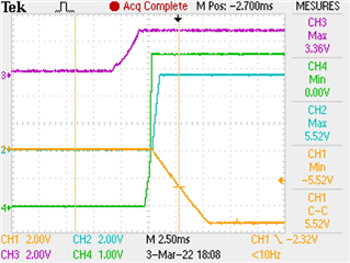
1 - On the following picture there is a spike on VNEG output which is not observed in the datasheet. What can be the cause?  

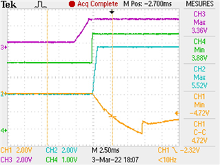
2 - When the device is powered off and powered-on before VREG reach 0V then VNEG does not start correctly and then stays incorrect (about 1.86V which is outside the specified range). 

Is it expected that VREG remaining voltage level impacts VNEG startup? Please note that VPOS is correct.  

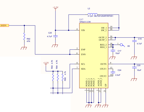
Current schematic for ref. is


Thank you in advance for your time.

Best regards,

Benoît,


  • Hello Benoit,

    I reviewed the schematics and it looks good. I suspect that the transient in the first scope plot could be due to spike in load current beyond 40mA.Also, I would not expect residual voltage on the VNEG rail to cause the startup problem shown in the second scope plot in your post. I suspect this also to some artifact of the load current at startup. Can you please remove the load from the board and see if the anomalous behavior goes away? i.e. measure the same scope plots but without the load attached.

    Kind Regards,

    Liaqat

  • Hello Liaqat,

    Thank you for your answer.

    Just to complete my previous message. TPS65132 -5.4V VNEG power rail is intended to power a -5.0V LDO to supply analog components. 10µF is set on -5.0V LDO output (same as the one mentioned on the schematic above (C20)). Power consumption on VNEG -5.4V is 15mA once the system is running. I don’t know what is the peak value during startup condition.

    First test was to remove the load as you suggested (-5.4V VNEG not connected to -5.0V LDO). There is no spike, TPS65132 works as expected.

    Second step was to connect -5.4V VNEG to -5.0V LDO input. 10µF on -5.0V LDO output is removed. Spike is still here but smaller than our default configuration.


     Purple: Vin, Green: VREG, Blue: TPS 65132 5.4V output, yellow: TPS 65132 -5.4V output

    In this configuration we still can observe an incorrect value on TPS 65132 -5.4V output. Picture below shows an incorrect TPS 65132 -5.4V output while there is 3.88V on VREG. Previous picture shows a correct TPS 65132 -5.4V output while there is 0V on VREG. Perhaps it is a coincidence but further to our tests it is reproductible.


    Purple: Vin, Green: VREG, Blue: TPS 65132 5.4V output, yellow: TPS 65132 -5.4V output.

    Thanks for your consideration on this.

    Benoît,


  • Hello Benoit,

    Since TPS65132 works as expected when load is disconnected, I strongly suspect that load current is much higher during start up than the nominal 15mA during normal operation and that is what is causing the spike and anomalous behavior on the VNEG rail. The fact that removing the 10uF at the output of LDO reduced the spike also points to the same logic of higher load current during startup because the LDO was charging the 10uF capacitor during startup when it was there. So this all makes sense. You will somehow need to reduce the load current on VNEG during startup of your system for it to work.

    Kind Regards,

    Liaqat

  • Thanks Liaqat for your time and answers. I will investigate the current startup condition to see if I'm over the 40mA specification. 

    Best regards, 

    Benoît,  

  • You are welcome and please let me know if there are any questions.

    Kind Regards,

    Liaqat

  • Hello Liaqat,

    To investigate further our design we decided to use TPS65132W evaluation board. It is powered by external 3.3V power supply (current limited to 3A). TPS65132W is configured to output +/-5.4V. A load to draw 37mA is attached to each TPS65132W outputs (outp outn).  

    +5.4V starts correctly but -5.4V does not (about -3.44V).From this situation, when the load is then disconnected from outn(-5.4V), TPS output voltage reaches the correct value. I then reconnect the load and the voltage remains correct and the 37mA are delivered without any problem. Same thing observed whatever the sequence of EN pins is. Same behavior in 40 and 80mA modes.    

    In the datasheet, table 12 mentions that figure 39 to 42 are at no load. Do you know if there is a limitation on the load at start-up?

    Note: -5.4V seems to start correctly on our EVM board from 500Ohms load. At 390Ohms outn(-5.4V) only starts correctly when the device is configured in 80mA mode.   

    Thank you for your help.

    Best regards,

    Benoît,

  • Hello Benoit,

    The behavior you are observing is expected. The soft-start section for negative charge pump (CPN) in the datasheet talks about the limited current during initial power up. If full load is active during initial charging phase of the output capacitors, the limited charge current is not able to achieve the set output voltage. So the charge pump is not able to regulate into a fully active load at power up.

    Kind Regards,

    Liaqat

  • Hello Liaqat, 

    Thanks for your reply. Are you referring to "For TPS65132B2, TPS65132Lx, TPS65132Tx, and TPS65132Wx, the typical ramp-up times are slowed down by a factor of 4 (i.e 12.5 mA and 25 mA typical output current for 40mA and 80mA modes respectively) and the inrush current is also reduced by a factor of about 4."

    If yes, I misunderstood the datasheet. I thought that it was the device that limited the current at start-up without having limitation on the load as long as we are below the 40mA limit. Do you suggest that we have to implement a circuit that disconnects the load as long as the outn voltage is not reach?

    Could you please confirm that outp is not subject to this limitation ? Thank you. 

    Best regards,

    Benoît,     

  • Hello,

    Yes, I am referring to the datasheet excerpt you copied above. The device has to reach voltage regulation during soft-start phase for the negative charge pump before it can deliver full load current. So any down stream load should not be enabled before inverting charge pump reaches regulation.

    Kind Regards,

    Liaqat