Yes, you can use a low side driver as a high side driver! There are a few ways to go about this:
- Bootstrap Bias Supply
- Isolated Supply
- Pulse Transformer
Bootstrap Bias Supply Solution:
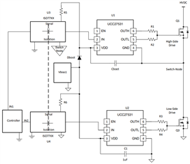
A bootstrap bias supply can work to create a high side driver using a low side driver in a very similar way to a half bridge driver. Looking at the example schematic below, we see that the driver used on the high side “Ground” is referenced to the switch node with a bootstrap capacitor and bootstrap diode to provide sufficient bias to drive the high side MOSFET. Because the driver on the high side is referenced to a moving reference (the switch node), the input signal of the driver must move along with this reference too. Therefore, a signal level shifter that is referenced to the switch node is needed. This can be done with using a capacitive signal isolator or an opto-isolator. The example circuit in Figure 1 uses a capacitive signal isolator.

Figure 1: Bootstrap Bias Solution with Signal Isolation
The bootstrap supply solution does come with a duty cycle limitation due to the boot strap circuitry discharging to keep the high side biased (and then needing the low side to turn on again to recharge the bootstrap capacitor).
Single channel, low side gate drivers such as TI’s new UCC27614 is a great choice here.
(For further detail, please reference: https://www.ti.com/lit/an/slua669a/slua669a.pdf)
-------
Isolated Supply Solution:
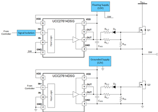
Another route of using a low side driver as a high side driver is by supplying the driver on the high side with an isolated power supply that is referenced to the switch node. This solution does not require a bootstrap diode and is able to provide 100% duty cycle operation. Note: a capacitor should still be used to bypass the floating supply. Signal isolation or level shifter is still required for the high side input signal. Figure 2 shows an example of how a floating supply can allow for a low side driver to be used in a high side configuration.

Figure 2: Isolated Supply for High Side with Signal Isolation
-------
Pulse Transformer Solution:
Pulse transformers are another solution that can be used to create high side and low side bias (half bridge topology). The pulse transformer topology comes with many built in advantages:
- Isolation
- Functional and/or safety
- Power and Signal Transmission
- Eliminates need for a gate bias supply on the secondary side
- Negative Bias Capability
- Secondary of transformer will swing + / -
- Can choose to use negative bias for SiC or IGBT switches
- Or eliminate negative bias with diode and PNP BJT (see example circuit below)
- Voltage Scaling
- Choosing different turns ratio for transformer can scale voltage up or down
- Secondary of transformer will swing + / -
Using a pulse transformer does come with a typical limitation of being restricted to operating at a 50/50% duty cycle. So, the pulse transformer topology is ideal for frequency-controlled applications such as PSFB, Motor drives, Intermediate bus converters, and LLCs.
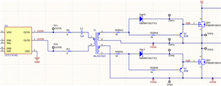
An example circuit of a pulse transformer topology is shown below in Figure 3 (Using UCC27624 and both of its channels to push and pull on the primary of the pulse transformer):

Figure 3: Pulse Transformer Example

