


We're designing a battery management board based on this schematic (refer to Figure 1, page 4) for the BQ7625 and the MSP430G2xx2. In designing the schematic, we ran into a few components which we were unsure about:
- What are NA components? (Specifically, we were wondering about R30 in the load removal circuit.)
- Should we place the zero-ohm resistors, or could those be approximated using a wire? (For example, R11 and R12 are marked as having zero resistance.)
- D5 in the hold-up circuit has double lines -- is this any different than a regular zener diode?
- How should we select RIN values depending on our power consumption and application?
- How does RSENS1/RSENS2 parallel resistors differ from a single resistor in the current sensor circuit? (see picture below)
- What are SMBUS and COM in the Display Button Detection circuit?
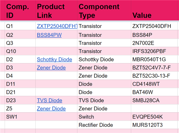
Also, the table below is a list of obsolete/unavailable components (the component numbers refer to the circuit diagram in the linked datasheet). Are there any recommended alternatives to replace these components?

Thanks for your help!
