This thread has been locked.

If you have a related question, please click the "Ask a related question" button in the top right corner. The newly created question will be automatically linked to this question.

Using LDO with shunt resistor

Other Parts Discussed in Thread: TPS76201

Hi guys,

I'm designing a circuit for power profiling of MSP430. I want to measure the voltage drop across a shunt in the supply line. For the voltage regulation, I will use the TPS76201. In the data sheet, page 8/15, the equation to calculate R1 and R2 out of vref and Vout is given.

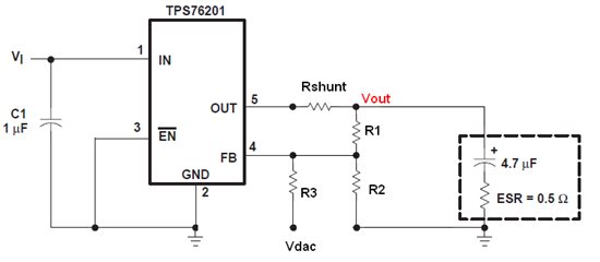
In my case, I have a shunt resistor between the output of the LDO and the point, which voltage I want to regulate (Vout)

Vdac is the output voltage of a DAC, based on which the supply voltage Vout is set. It goes from 0V ... 2,5V.

I want to setup Vout from 0.9V ... 3,6V


How can I choose R1, R2 and R3?


Thanks

  • What are your electrical requirements (Vin, Vout, Iout) and what made you chose the TPS76201?  It works fine but we have many newer LDOs that do not require a tantalum output capacitor that can be expensive.

    For an LDO, the output current is equal to the input current, neglecting the ground pin current which is small.  So, it might be better to put the resistor on the input of the LDO, before the input capacitor C1.  In this way, the output voltage will not be effected.

    For your circuit, with or without the Rshunt, R1, R2, and R3 can be found by writing the equations for a current balance on the FB pin.  The FB pin will always be regulated to 0.6663V.  And the recommended value for R2 is 66.5k.  So, R1 and R2 can be solved based on the desired range of vout based on the range of Vdac.