This thread has been locked.

If you have a related question, please click the "Ask a related question" button in the top right corner. The newly created question will be automatically linked to this question.

TPS54339: Soft Start Control, Shortest Start Up Time

Part Number: TPS54339

Hi,


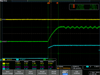
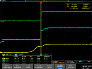
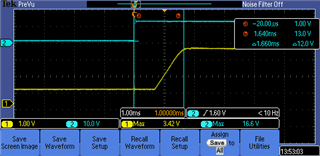
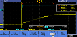
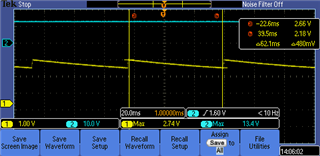
Are there minimum capacitance values or minimum start up times for this part? When I try to use a capacitor that is smaller than 6.2nF, the start up starts to look parabolic (left side of an upside down U) instead of a straight line rising up and I start to see jagged output values with a period of about 60ms. The rise time will also be a lot longer, in the several ms range once I decrease capacitance less than 5.2nF. Why is that?

 In the attached picture, you can ignore channel 1. Channel 2 is the output, and channel 2 is the enable. This is for a 4.7nF SS cap without any load, so excessive load is not the issue.

Thanks,

  • Hi Sharon,

    The datasheet does not state any limitation on the SS cap min value. But I am checking with the design team for any additional details they can provide. Can you share details on your schematic? What is the expected VOUT and are you regulating at that value with a smaller SS cap? From the scope shot, it looks like the VOUT is not steady but I cannot see details as the timescale is quite large. Can you also provide a zoomed in scope shot?

    Thanks,
    Amod

  • Hi Amod,

    I am using the TI EVB with the feedback resistors changed to provide an output of 3.3V (R1=82.5K and R2 =24.9K). I changed the inductor to a different 2.2uH inductor (Coilcraft XAL5030-222ME) that has close to 10A saturation, though I don't have any load on it so the issue likely is not with the inductor.

    Other than that, I changed C6, the SS cap to 4.7nF. Input voltage is 13V from a power supply, with a 3A current limit.

    I can take another scope shot that is more zoomed in at a later date but if you could provide feedback before then about minimum SS cap values, that would be great.

    Thanks!

    Sharon

  • Hi Sharon,

    Yes I will provide updates from the designer on this. The scope shot is zoomed out so cannot confirm but is the VOUT regulating to 3.3V? Especially in the jagged area. Does the same design with a larger CSS work fine on your measurement setup?

    Thanks,

    Amod

  • Hi Amod,

    With any CSS 6.2pF or larger, the Vout rises in a straight line and is very stable at 3.3V. I've attached another scope shot with a 8.2nF CSS. In the original photo, it is not able to rise to 3.3V.

  • Thanks Sharon. I do not have an EVM handy with me to check this but will relay the feedback from design on this. Even with no load, it may be possible to run into current limit during startup. If you have the extra time, would recommend checking inductor current waveform. 

    Thanks,

    Amod

  • Hi,

    Sorry for the late reply. I fried my board and was waiting for a new one. I have waveforms now below for the new board. They look a little bit different than the old one so I am reattaching all waveforms.

    Yellow(1) is the VOUT and Blue(2) is the EN

    1. regular start up with 8.2pF, feedback resistor changed to output at 3.3V, inductor changed to a different 2.2uH inductor (Coilcraft XAL5030-222ME) same changes as before

    2. SW node with 8.2pF

    3. start up with 5.6pF

    4. steady state with 5.6pF

    5. SW node with 5.6pF

    Please let me know if you've heard anything back from the design team.

    Thanks.

  • Hi Sharon,

    Are you actually using 8.2pF and 5.6pF or 8.2nF and 5.6nF? What is the tss you are trying to design for? Did you manage to check the inductor current waveform to see if device hits current limit? The design simulation is running into technical issues and they are trying to resolve it but that could take a while. I have ordered a TPS54339 EVM to test also. Once here, I can try these conditions as well.

    Thanks,

    Amod

  • Sorry typo on my last post. Those should all be nF, not pF. 

    I'm hoping to get 0.6ms from EN high to VOUT high, which is about half of the lowest timing I can currently achieve without the rail collapsing [with 6.2nF, I can achieve 1.2ms].

    I have not checked the inductor current waveform. Maybe I am not understanding but I would be surprised if the current is reaching 7-9A without a load, when it cannot reach 3.3V? Am I missing something?

  • Sharon,

    Thanks for sharing the updated units on the cap. Current limit minimum is around 3.5A on this part with typical around 4.1A both of which can vary from part to part. It is possible that even without any load during startup you may run into current limit but the device should be able to recover and provide the 3.3V.

    Is there no switching activity on the SW node waveforms? If you are using TPS54339 which has FCCM operation, you should see switching activity with frequency around 600kHz during steady-state. Are you using the TPS54339E by any chance? TPS54339E has eco-mode and can lower switching frequency with lower loads (no-load condition here that you are using). If you increase the load to higher values like 100mA or so, you can check to see if the device regulates with FCCM or in eco-mode (DCM). 

    Thanks,

    Amod