This thread has been locked.

If you have a related question, please click the "Ask a related question" button in the top right corner. The newly created question will be automatically linked to this question.

UCC256404: Inquire about VCC

Part Number: UCC256404
Other Parts Discussed in Thread: UCC256403

Hi TI experts,

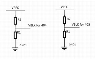
We want to use it like the attached block.

1. When designing the two controllers, is it available for VCC sharing? 

Two-UCC256404-Connection.pdf

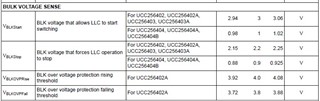
2. We are simulating using the UCC256404 Simplis Model File. During the simulation, there are restrictions as follows.

Is there a simulation file that has no restrictions? If there is, can I get it?

Please check my questions.

Thank you.

Downey Kim.

  • Hi Kim,

    Thanks for reaching out to us. 

    You should be able to share the same auxiliary winding for both the controllers. Also you can share the BLK pin too. 

    One point needs to be pointed out that, UCC256404 will start switching only after VCC reaches 26V.  Also, UCC256404 HV pin must to be connected to rectified AC to detect the zero crossing. otherwise , controller keep injects the x-cap discharge current. So, to satisfy these conditions, Its recommended to share the rectified AC voltages too.


    We can only provide the simplis file which is already available in the website. Please let me know if you have nay further qutions. 

    Regards

    Manikanta P

  • Hi Manikanta,

    Thanks for your help.

    If we design UCC256404 + UCC256403, Can we use that just have to share the VCC without sharing the HV pin?

    Thanks.

    Downey Kim.

  • Hi Kim,

    That should work too.

    However, one thing needs to be pointed out that, in this configuration, the converter that uses UCC256403, will start much earlier because VCCStartSwitching for 403 is 10.9V, whereas for 404 it is 26V.

    Regards

    Manikanta P

  • Hi Manikanta,

    We decided to design UCC256404+UCC256403.

    Can I configure the circuit with VCC and Zener diode instead of High Input Voltage on BLK pin? The reason is to reduce standby power.

    Please check it..

    If there is another way to reduce standby power, please suggest.

    Thank you.

    Downey Kim.

  • Hi Kim,

    This is not a good option.

    In this topology scheme, second LLC with the 403 controller starts switching as soon as BLK pin reaches BLK start while VCC capacitor is charging. So, PFC output voltage wont built up by the time zener voltage reaches BLK start voltage. So, this LLC hit OCP fault.

    Ideal power sequence for LLC is

    1. PFC output voltage should be close to nominal voltage and then LLC should start switching. This way stresses across the components would be less.

    I would recommend you to use the topology that I suggested in my previous thread.

    Please let me know if you have any further questions.

    Regards

    Manikanta P

  • Hi Manikanta,

    Thank you for your advice.

    We have one concern. VBLK of UCC256403 and UCC256404 is different. 

    Can I share BLK pin? Is there any problem if I share the BLK pin?

    Please check. 

    Thank you!

    Downey Kim.

  • Hi Kim,

    I completely missed that point. I am sorry about that.

    If you use the 404+403 controllers with same BLK resistor bank, the implication would be the power stage with 403 controller, need to operate at the much lower input voltage than the power stage with 404 controller.

    For example, lets say if you use the same resistor bank for both the controllers as show below:

    The stop voltage for second controller coming to be 264V assuming the startup voltage for both the controllers are 360V.

    If you keep the startup voltage as 390, the stop voltage would be 286V.

    So you need to make sure the 403 controller's power stage can withstand those lower voltages.

    If you use two separate resistor banks with the same PFC bus for the BLK pin, the results would be shown below. I don't see much difference from the previous case.

    Regards

    Manikanta P