Hello,
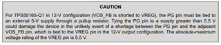
My customer wants TI review of their TPS55165-Q1 circuit design.
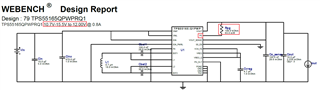
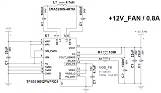
Could you please review the following circuit design?
- VIN = 15.6V ~ 10.7V, VOUT = fixed 12V
Thanks,
JH
Hello,
My customer wants TI review of their TPS55165-Q1 circuit design.
Could you please review the following circuit design?
- VIN = 15.6V ~ 10.7V, VOUT = fixed 12V
Thanks,
JH