This thread has been locked.

If you have a related question, please click the "Ask a related question" button in the top right corner. The newly created question will be automatically linked to this question.

LM2596: step down regulator capacitors selection

Part Number: LM2596
Other Parts Discussed in Thread: LMR23630, LM2676, LM76003, LM46002, LMR33630, LM22676,

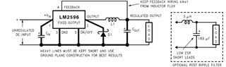
I was planning to use the LM2596S-5.0/NOPB to convert 24V to 5V from a bank supply. I am designing a PCB that will work with 5V and 3.3V.

This card has an MCU32 with an Ethernet interface that processes requests from a host. The uC reads the status of 3 inputs or write to 3 outputs and exchange data it with PC. There is not much more electronics.
This card will be located inside a metal articulated arm that is part of a test bank. This arm is expected that it will be connected to the test system 20-24 hours a day. 
I had thought to use this regulator to get 5V. Keeping this in mind:

I was following thedatasheet instructions to select the components and I find that this regulator requires capacitors with VCIN = 35V:50V. If you want to use a CIN = 100uF, the only possible option is to use aluminum electrolytic capacitors. I have observed that the useful life of this type of capacitor for 50V does not exceed 3000h.

The working conditions force a circuit configuration using electrolytic capacitors. But these capacitors cannot offer more than 3 months of service life. So it seems that the circuit may take 3-4 months to show behaviour anomalies or missfunction.

Ceramic capacitors are not recommended, according to the datasheet, because they can produce ringing on Vin. There is no variety of inexpensive tantalum capacitors for 100uF and Vcin >= 35V.

-Can you suggest other capacitors for Cin and Cout in my case?
-Or should I discard this device for these operating conditions?

I would like to add that I don't know which value for Cin using tantalum capacitors will work here instead of Electrolytic. Since the only values that matches:

  • Vcin = 2xVin, so 50V, 
  • highest Irms for ILoads under 1.5A

Are those being less than 16uF. So I don't know if 10uF or 16uF tantalium capacitor will fit here to get best results. Datasheet talks about 680uF for electrolytic capacitors, but it doesn't give any values for tantalum option. I can't achieve more than 15uF with V= 50V. It seems to be a little far from them. 

When I say if there is another option I'm refereing to this type of solution in ex: Cin = 15uF, 50V, Irms = 1A, and low ESR smd tantalum capacitor. 

But there could be such more. 

Thanks in advance. 

  • Hello

    For the input capacitors you could use a combination of ceramic and Al.  

    Something like a 22uF Al. and a 47uF ceramic may be enough.

    The reason for specifying an Al. output capacitor is related to the loop stability.

    This device relies on the ESR of the Al. output capacitor to help establish a stable loop.

    You may be able to use two or more 47uF ceramic capacitors on the output and use the CFF capacitor

    to adjust the loop response for a stable robust loop.

    All of the above would have to be carefully tested on the EVM to ensure a robust design, since you are looking at

    a high rel. application.  I would not rely on a simulation as a substitute for bench testing, since this is a rather old

    device.  The bench testing would involve a Bode plot and load transient testing to ensure a stable and robust loop.

    Also, start-up testing should be done, since you would be using a CFF in the design.

    Depending on your output current requirement, we have many devices that work with ceramic capacitors, both on the 

    input and output.  You might want to look at:

    LM2676, LM22676, LMR33630, LMR23630, LM76003, LM46002

    Or other members of the above family.  These would provide better efficiency than the LM2596.

    Thanks

  • Thank you for the answer. I will take a look at your devices suggestions.

    Does "Al" mean: Aluminium electrolytic? 

    3 question related with your comments:

    I was worried about aluminium electrolytic cap life time. Are they a good sollution if the device is connected (more than 8 hours a day)? I need to get a pcb that ensures the equipment will be working more than 6 months. They will be sold and costumers hope to pay for equipment that works for more than some months. I see that those capacitors are classified by life time for hours. Being typically 3000h the most common value.

    • 3000h/20h/30days --> 5 months. 

    1.- Are the electrolytic less reliable than tantalum after some working months? -Sorry for my ignorance related to this point-

    2.- I have no problem by choosing output elements because of datasheet table suggestions for fixed Vout = 5V. But talking about Cin: Are you telling me that Al 22uF + ceramic 47uF could be good for Vin = 24V and fixed Vout = 5V? 

    3.- Could you tell me whether tantalum 15uF is too much short value for this circuit conditions? 

    thanks for your attention, 

    best regards

  • Hello

    Yes, Al. is aluminium electrolytic.

    I really can not comment on the reliability of Al. caps in your application.  You will need to consult

    with your reliability experts inside your organization.

    1. Again, I would not be able to comment

    2. That combination of input cap I suggested may be adequate.  You will need to carefully test it to be sure.

    3. I think that 15uF is a bit too small for this device.

    Thanks

  • Thanks Frank, your answer has been very useful for taking a decition. Just for closing the conversation; I need the last clarification from you. 

    When you said: 

    "Depending on your output current requirement, we have many devices that work with ceramic capacitors, both on the 

    input and output. "

    Were you refering to:

    "You might want to look at:

    LM2676, LM22676, LMR33630, LMR23630, LM76003, LM46002" ?

  • Hello

    Yes; those are a sample of devices that you might want to look at.

    Thanks