This thread has been locked.

If you have a related question, please click the "Ask a related question" button in the top right corner. The newly created question will be automatically linked to this question.

TPS53832: I3C/I2C interface communication issue

Part Number: TPS53832

Hi TI expert,

Our DDR5 RDIMMs use TPS53832 as PMIC. When we do the following opeations on the I2C/I3C bus,

1. read PMIC register in I3C mode - suceessful

2. bus reset 

3. read PMIC registers in I2C mode - suceessful

4. SETAASA

5. read PMIC register in I3C mode - fail

6. bus reset

7. RSTDAA 

8. read PMIC registers in I2C mode - suceessful

9. SETAASA

10. read PMIC register in I3C mode - suceessful

 It's strange that I3C read opeation in step5 fails. If RSTDAA in step7 is inserted, the I3C read opeartion in step10 is successful. I don't think RSTDAA is necessary, but the reality is that the switching operation between I2C and I3C fails without this procedure (as step 1~5).

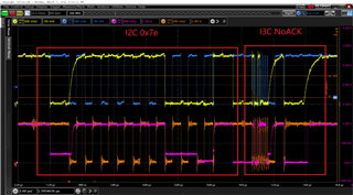
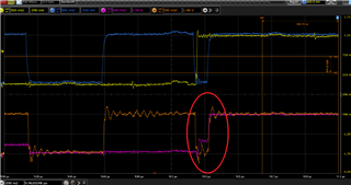
The following pictures shows the waveform in step5. The upper two signals in the screen are on hub host side, and lower two are hub local side(which are connected to PMIC and let's just focus on these two).

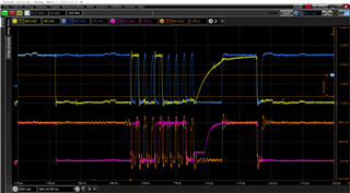
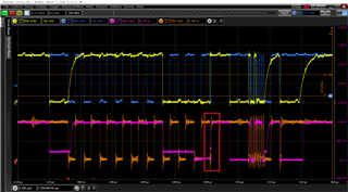
There is no ACK on I3C, and we found a very strange "step" on the data signal in the red circle in the scope screen capture.  

The following is a zoom-in view on the circle.

We did the same experiment with IDT PMIC and it works quite well. It means that I3C read operation in step5 is successful for IDT parts.

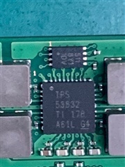
The below picture shows the TI parts on the DIMM.

Please feel free to let me know if there is anythin unclear. 

Looking forward to your reply. This issue has been bothering us for quite a long time and has seriously affected the progress of our project.

Best regards,

Shaoyuan Zheng

  • Hi

    Before step 1, how do you let the device enter I3C mode with a successful read?

    How long was the SCl hold low before release? this is to ensure that bus reset does take effect.

    After a bus reset, the R34[3:1] is set 111b based on JEDEC spec. but the captured waveform has address 0xFC(1111 1100b -> 111 1100b) which did not match the 111b defined by the R34[3:1].  Please compare this with a good I3C reading waveform to see whether the address is right. if address is not right, NO ACK is what expected.

    Regards

    Yihe

  • Hi yihe,

    Thanks for your reply. Please find my answers in below lines.

    Q1: Before step1, we do the following operations:

    a. system cold reset

    b. Bus reset and enable VR

    c. DDR PHY training in I2C mode

    d. SETAASA 

    Q2: SCL is driven to low voltage for ~100ms during reset, please refer to the following scope screen capture.

    Q3. In step5, 0x7e is sent in 1MHz speed, which followed by I3C mode read on slave_address=0x48, reg_address=0x32. The lower two signal in the picture are for local side probe.

    The following is the zoom-in view on I3C operation.

    We also captured the waveform on IDT devices which works as expected. Totally the same opration as above, and we can see ACK and read-back data transmition in the below scope screen scope.


    Thanks,

    Shaoyuan Zheng

  • Hi yihe,

    Please let me know if there is any update or you need any more information.

    Thanks!

    Shaoyuan Zheng,

  • Hi 

    There is a email discussion on this issue from quanglong Fu. we will discuss this in the email instead of on the forum

    Regards

    Yihe