This thread has been locked.

If you have a related question, please click the "Ask a related question" button in the top right corner. The newly created question will be automatically linked to this question.

BQ40Z50: Reverse cell(s) connection protection

Part Number: BQ40Z50
Other Parts Discussed in Thread: BQ34Z50

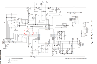
We are planning to incorporate the BQ40Z50 for our design. We are now thinking production wise, how to protect the ready PCB from incorrectly mounted cells as the last step. Please consider the following block diagram from the DS:

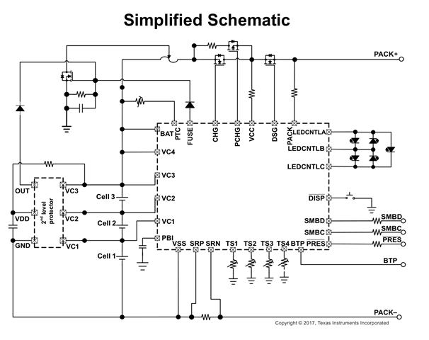
What will happen if all 3 of the cells, or only some of them will be connected in reverse polarity? What impact will it have on the BQ34Z50 itself and the circuitry connected via PACK+ and PACK-?

I would appreciate all feedback!

  • Hello Lukasz,

    The BQ40z50 has some PF conditions that should be able to blow the fuse and close both the chg and dsg fet in this condition. Ideally this could save the pack+ and pack- circuitry. However, a negative voltage will violate the absmax ratings of the pins (VCx, and BAT depending on which/how many cells are reversed). In addition, I'm not sure that the gauge would be able to survive long enough to drive the fuse pin. This would be very likely to damage the device.

    You can include a Schottky diode like so, which may prevent some damage in the case where the whole pack is reversed. But, it would still violate the abs max of the VCx pins so I can't say with certainty that the gauge would survive. There may be a way to prevent any of the pins from seeing a negative voltage in the case of reverse connection, but it would require extra circuitry. I also wouldn't recommend adding a bunch of diodes because that will effect gauging. Let me know if you have any other questions.

    thanks,

    Alex M.

  • Hi Alex, thank you for the answer.

    Correct me if I am wrong, but I would expect the pack+ and pack- external circuitry to stay safe in case of an incorrect cells connection (any), as the bq40z50 would die or at least not turn off, thus, no voltages on the mosfet gates?

    Using any diodes in series is not an option for us, as we i tend to pass around 20A through, which would induce a lot of power losses.

  • Hello Lukasz,

    That sounds correct, they should both be normally off if unpowered. The default on start up is also for them to both be off (XCHG and XDSG high). So you should be safe in that respect. And because the body diodes are oriented in opposite directions, that should be no issue either.

    As for the protection circuit, maybe one of the FET options in here would be okay? I can only answer gauge-related questions, so I can't really help with any protection circuit design.

    best of luck,

    Alex M.

  • Hi Alex,

    Ok, so from the pack perspective we are safe. Now:

    1. In case the complete string is reversed, the bq device dies.

    2. In case any of the single cells are reversed, the device dies as well- is this one correct too?

    Thanks for the links. We would like to avoid any in series devices (diodes, fets), as they would i troduce power losses. Also, adding such for each single cell (we would have 4) would have some cost and design impact.

  • Hello Lukasz,

    The device may not actually die in either case, but since the absmax is violated there is no guarantee. In addition, it is possible the VCx pins could be compromised while the device keeps working. In any case, I think it would be best to treat a device that sees this condition as compromised and avoid using it whether it dies or not. 

    thanks,

    Alex M.

  • Hi Alex, understood.

    Production wise, what is the correct approach to integrate the cells into the device? Assuming the board is manufactured, and now, as the last step, each cell has to be soldered to the pcb. Assuming 4S pack, should each cell be soldered one by one starting from the bottom cell?

    In case the pack cells come presoldered (4S string is togehther), is there any requirement on how to solder it to the pcb (difficult to guarantee bottom cell gnd touches the board first.

    Can single cells be desoldered during the others are still connected?

  • Hello Lukasz,

    Ideally, it would be connected from the GND pin up to the highest cell in order. However, it isn't really too important what order it goes in. The inputs are fairly robust in terms of positive voltages, if you refer again to the absmax ratings for the VCx pins, they can handle up to 30V from ground. Nothing should break if one was left floating from being desoldered. Since the remaining batteries are referenced to the floating node; they should still have a voltage on the pins within spec. 

    thanks,

    Alex M.