This thread has been locked.

If you have a related question, please click the "Ask a related question" button in the top right corner. The newly created question will be automatically linked to this question.

BQ28Z610: learning Cycle don't complete

Part Number: BQ28Z610
Other Parts Discussed in Thread: GPCCHEM, BQ24120, BQSTUDIO

I'm working for learning cycle with a sistem based on 2S li-ion, battery charger BQ28120 with 150mA charging current

 - select the chemid with GPCCHEM tool

- program on the EVM : CHEMID, and design parameter as suggested by SLUA 777

- start discharge, relax, charge relax and so on for learning cycle

I repeat more time the cyces but do not complete the lerning.

Attached the logfile.2110.charger.zip
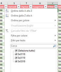
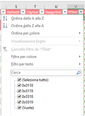
  • Hello Stefano,

    I looked in the log and I see that the learned status has remained at 4 the whole time, which means that the Qmax update isn't happening. I looked at all the flags/bits and it seems on your second cycle, everything is correct besides the FC bit not setting. A .GG file would help here, but you can just double check the charge termination configuration. You want to have it set to use charge termination and ensure the taper voltage and current are set correctly. You are charging your 2S li-ion pack to 7780mV, which is a bit low for li-ion. I would expect termination to be just above 8000mV, unless you are using a different(lower voltage) chemistry. To save time, I would suggest messing around with the charge termination settings (voltage and current) until you can get the FC bit to flip, and then go through the whole learning cycle process. That way you will save time from discharging and relaxing repeatedly. 

    thanks,

    Alex M.

  • Hi Alex, thank you for answer.

    About termination voltage of the charger: for the test I'm using BQ24120 and effectevely the TCC timer is too low and terminates the charge. Now I've increase the timer and start again. 

    About FC:

    - this flag is setted if the voltage of the battery is higher than Set Voltage Threshold (ADD: 0x463b) , it is correct ?

    - in my application 2S this mean that each battery must be higher of FC_SVT; it is corrct ?

    - for setting the FC  Voltage Threshold, must be considered the tollerance of final Voltage of battery charger and decrease to 4100 mV, are you agree ?

    - we are evaluate also coke anode battery, in this case the final voltage is slightly different

    Attached the gg file, 

    I'm charging now; I will inform after relaxing time

    Than You 

    Regards

    Stefano 

    15032022.gg.csv

  • I saw now a problem :

    - tha battery voltage is lower than pack voltage 

    - the real value  is 8322mV

    - also the batteries  voltage are wrong; the real value is 4128mV

    Now I wil permorm a voltage calibration of the board and start again because the charge are terminated but the FC remain low.

  • Hello Stefano,

    The voltage calibration sounds promising, let me know if you have any success with FC after changing them. Here is a quick explanation for the conditions:

    You can set both TC and FC to trigger off a voltage threshold, RSOC threshold, or a valid charge termination. For the learning cycle, you won't want to use SOC-based termination because it won't be accurate. VCT is the most comprehensive FC bit for this purpose (and the default), so I would recommend trying to make it work. As you can see in this table, it isn't that each cell has to be higher, but that the max of either is within the set charge range. 

    In advanced charge algorithm, so can set the charging voltage threshold for each temperature range. At room temp, you have 4200mV, so the pack wants to see 8400mV. Of course, it is divided by 2 again and compared to the max of the two cells + 75mV as you set term voltage. Based on your logs, this condition is not happening, and definitely a prime suspect for the issue. So I would recommend these steps:

    • Re-calibrate and see if that fixes the voltage mismatch
    • turn off charge balancing until the learning cycle is done
    • Go into advanced charge algorithm and enter values based on your system
    • Go into SOC Flag config A and ensure you are using VCT for charge term
    • Try charging and discharging until you can get the FC bit to set correctly; don't do the entire learning cycle/resting if you can't guarantee a charge term
    • Re-do the learning cycle

    Hopefully with this, you will be able to perform the learning cycle. Let me know if it still isn't working for you after trying this/calibration issues show up. 

    thanks,

    Alex M.

  • Hello  Alex, bad news.

    I have disable the CB in balancing configuration  and FCSETVCT is enable; the FC Set Voltage Thresholds is 4120 mA and the two batteries have pased this value but the FC continue to be low.

    Attached log file e register setting

     16032022.gg.csv16032022_Charge.zip

  • Hello Stefano,

    thanks for providing the logs. It looks like you are very close here, let me show show a plot of the data to explain:

    Remember there are three conditions for successful charge termination to be detected when using VCT:

    • Max of either cell 1 or 2(V1/V2) + 75mV > charge term voltage (CTV) -> your gauge clears this condition first and stays well-over
    • Average current < Taper current threshold -> Your gauge does not meet this until current totally turns off, but does meet it
    • Accumulated change in capacity >0.25maH -> you don't appear to meet this condition

    Also, when using VCT mode, the FC set voltage threshold doesn't do anything. If you'd like, you can set TC to set based on the TC set voltage threshold to see that behavior and if you like how it detects fully-charged condition. I think the simplest way to ensure this triggers though, is to raise the taper current threshold. You hit conditions1 at about 8000 seconds, and don't hit taper until about 15000 seconds. Simply increasing the gauge's taper current threshold seems like it should allow VCT to trigger. I would try something from 30-60mA; the lowest that works consistently. That should help you meet the accumulated charge condition. You also may want to increase the charge voltage(CTV on my plot) because you clear the threshold by a lot and hit it a bit early. Please let me know if this fixes it for you.

    thanks,

    Alex M.

  • Hi Alex,

    I see the the taper current problem; this morning start a charge woth 50 mA setting. Where do you see the accumulated change in capacity ?

  • Update infos: Great !! FC bit setted !!! Attached the log.

    Before start the learning cycle have you some test for verify that the system is workig correctly ?

    If all it is oK , i need CB=1, GAUGE_EN=1, QEN=1, RDIS=1 and than I can start the learning; are you agree ?

    During the learning another fondamental point is the relaxing recognition; if this occours the OCVFR=1 but is it remain high ? If yes I can stop the learnig after this condition 

    Thank you

    Best Regards

    Stefano 

     17032022charge.log17032022.gg.csv

  • Hello Stefano,

    Congrats on getting the charge termination, hopefully the other steps work well for you also. For the accumulated change in capacity, I'm not aware of an easy way to see that value from the gauge. I just looked at the current read by the gauge to estimate. That condition is essentially checking if any current is flowing while you are tapering. It is mostly to prevent charge termination from being wrongly detected when charging is stopped suddenly, because the algorithm uses average current.

    For the learning cycle, I would recommend referencing this document:

    7043.Achieving the Successful Learning Cycle (1) (1).pdf

    In addition, the TRM for this part will have any information on bits you are curious about. For example the OCVFR bit you mentioned will indicate that the gauge took an OCV measurement in the flat region (the mid-range of SOC where the voltage doesn't change much while charging/discharging). During the learning cycle, you should not see this bit go high as you will take OCV measurements outside of the flat region. 

    I would also suggest disabling charge balancing until learning is done. The cell-balancing is based on SOC which is inaccurate until the learning cycle is done. I believe the gauge won't even try to cell-balance until it is learned, even if you enable it, but I haven't tested that. 

    Overall, I would recommend following this document as exactly as possible, and if the bits aren't setting as expected, logging and stopping to figure out why. I also think you should reset the gauge before beginning anything to ensure you are on a blank slate.

    Best of luck,

    Alex M.

  • Hi Alex, bad news.

    I have repeated more time the learning cycle but the cicle don't complete: when the battery is near 7V the bqstudio is shutt down and I'm not able to connect again. After 30-60 minutes I need press S1 button and than I can connect to the EVM.  It sems that there is a low voltage protection active.

    Attached the register21032022.gg.csv

  • Hello Stefano,

    Sorry to hear that. You didn't have this problem before? Maybe it is happening because of the recalibration that was done. There are undervoltage protections, but it doesn't seem like you should have triggered any of them with your voltage of 7V. I noticed in a few logs that your cell's voltages tended to be somewhat mismatched, so its possible one cell was significantly lower voltage and could have triggered the CUV protection. The best bet to figuring out what happened is to log the issue.

    Also, is this the initial discharge to empty the battery or the learning cycle discharge? if its just to empty the battery, you can try using a lower discharge current to ensure to voltage drop doesn't prematurely trigger CUV before reaching your terminate voltage. the learning discharge needs to be at least C/10 though.

    In your first log you sent me, it looks like you met all of the conditions for the learning cycle besides charge termination, so it seems like you should be close to achieving it now. I would recommend trying again while logging in case the issue happens again, but using smaller currents when possible may solve your problem.

    thanks,

    Alex M.

  • Hello Aex,

    You didn't have this problem before?

    No, I didn't

    here are undervoltage protections

    Can you tell me the register name ? 

    tended to be somewhat mismatched

    The Cell are mismatched but the voltage is higher than CUV protection (2500mV)

    Also, is this the initial discharge to empty the battery or the learning cycle discharge? if its just to empty the battery, you can try using a lower discharge current to ensure to voltage drop doesn't prematurely trigger CUV before reaching your terminate voltage. the learning discharge needs to be at least C/10 though.

    The current is higher than C/10; now repeat at C/10 but in this case the final discharge is reach this night and I cannot disconnect the load; the BQ opens the discharge fet but after few time, when the battery increase it reconnect the load and this cycle is repeated continously; can I avoid the load reconnection ?

    Attached the interrupted log.

    Thank you 

    Regards

    Stefano 

    21032022_logfile.zip

  • The current is higher than C/10; now repeat at C/10 but in this case the final discharge is reach this night and I cannot disconnect the load; the BQ opens the discharge fet but after few time, when the battery increase it reconnect the load and this cycle is repeated continously; can I avoid the load reconnection ?

    May be a solution the CUV_RECOV_CHG enable ? Howover the voltage battery is never drop after CUV (2500mV)

  • In the test of the week end it's clear that is triggered the CUV protection, so with CUV_RECOV_CHG may be resolve the automatic recover

    You can see more differences in two cells. I tried to change the two battery with new battery (same model) but the Update Status stay at 00 also with charge and discharge cycle

  • Hello Alex,

    CUV_RECOV_CHG setting has resolved the automatic recover issue.

    This morning the discharge at 80mA is terminated correctly, more than 5 hours ago,  VOK and RDIS are cleared but OCVFR is not setted and QMAX is not updated. Attached the log.

     2303_BQ28z610.zip

    From  SLUA903:

    The 5 hour wait time is a recommendation; the most accurate time is determine when the [VOK] and
    [RDIS] bits are clear, which can occur sooner than 5 hours. If the alternative method of disabling IT
    was used, IT enable command should be sent after the 5 hour wait time. This forces an OCV
    measurement to be taken, and because the cells are sufficiently rested, this OCV value is qualified for
    a Qmax update.

    Can I send IT enable command for forcing OCV ? I read the TRM but i have not find the sequence for sendting IT enable command

    There is a not clear situation:

    This is the register status where OCVFR is LOW but if I read the data Memory: IT gauging Configuration , I see OCVFR high; attached the dump

    8176.Desktop.zip

  • Hello Alex,

    CUV_RECOV_CHG setting has resolved the automatic recover issue.

    This morning the discharge at 80mA is terminated correctly, more than 5 hours ago,  VOK and RDIS are cleared but OCVFR is not setted and QMAX is not updated. Attached the log.

     2303_BQ28z610.zip

    From  SLUA903:

    The 5 hour wait time is a recommendation; the most accurate time is determine when the [VOK] and
    [RDIS] bits are clear, which can occur sooner than 5 hours. If the alternative method of disabling IT
    was used, IT enable command should be sent after the 5 hour wait time. This forces an OCV
    measurement to be taken, and because the cells are sufficiently rested, this OCV value is qualified for
    a Qmax update.

    Can I send IT enable command for forcing OCV ? I read the TRM but i have not find the sequence for sendting IT enable command

    There is a not clear situation:

    This is the register status where OCVFR is LOW but if I read the data Memory: IT gauging Configuration , I see OCVFR high; attached the dump

    0143.Desktop.zip

    About relaxing voltage: I'm check the log on field CellVolt1 and CellVolt2 and I see that the minimal difference of measure is 1mV; the required dV/dT for a valid OCV is <4uV/s this mean that the value CellVolt1 and CellVolt2 must be fixed for more than 250 sec. ; in the log I see fixed value for more than 600 sec; why the Qmax  not is acquired ?

    About OCV acquiring: in TRM I see this flow:

    The first test is: DSG Current Th > Current > Chg Current Threshold

    In relaxing phase, my current is 0  than cannot be higher than Chg Current th; can you explain ?

  • Hello Stefano,

    For the learning cycle to be successful you must have a 90% change in DOD according to the chem ID you programmed using the GPCCHEM tool. From looking at the log it looks like your cells are not balanced and the DOD0 (range 0 to 2^14) is not cycling 90% between the two rest periods.

    Make sure your cells are balanced when running the learning cycle, also make sure you are getting a 90% change in the DOD0 value.

    The OCVFR feature can be disabled in the data flash, from your description it looks like it's enabled but never being set which is the correct operation for a learning cycle.

    Sincerely,

    Wyatt Keller

  • Make sure your cells are balanced when running the learning cycle,

    Hello Keller, about cells balancing: these battery have this mismatch and for reducing the mismatch I need change the cells now I will try.

    About DOD0 change I would like to know how obtain 90% change.

    However now change the batteries and starts a charge,

    Thank You 

    regrdas

    Stefabno

  • I change both battery and the new are charged, without mismatch than discharge the batteries with GAUGE_EN=1, QUEN=1, RDIS=1 Tomorrow I will send you the logfile

  • Hello Stefano,

    If your learning cycle range is the same as your logs you submitted to the GPCCEHM tool, you should be able to get 90% change in DOD0 by performing the same kind of log.

    What often happens for customers is that they change the voltage range they used to find the chem ID when they do the learning cycle (or the batteries are not balanced, causing early termination and essentially the same result) which causes a smaller DOD range and the learning doesn't complete successfully.

    It looks like you have nailed down the process, once we get the full cycles of 90% it looks like it should be good for Qmax update.

    Sincerely,

    Wyatt Keller

  • Hello Keller,

    or the batteries are not balanced,

    As you can see in my previous logfile there is a mismatch in the battery; now I have change the battery with the new couple and start again the dicharge; attached the logfile

     23032022.zip

    This log file is acquired in the first discharge for this battery couple; now I start a fully charge cycle and try again a discharge.

    Now I'm working with a new couple of batteries of the same type and maker; need I submit again the new battery to the GPCCHEM tool ?

    90% change in DOD0

    Where you see this value in logfile ? DOD0_1 and DOD0_2 I think; This value are fixed in my logfile.

    DOD0 is it jointed with RemCap field ?

    I see a strange beavioure in the log file attached (old batteries discharges) on fields RemCap/RSOC/FullChgCap during discharge:
    At row 3104 the RSOC drop from 72 to 0; the batteries are effectively tf end of discharge but this mean that RemCap it is started from too higher value, keep in mind my batteries are 700mAh but RemCap start from 2472, is there some wrong setting  ? 

    3323.BQ28z610.zip

    If your learning cycle range is the same as your logs you submitted to the GPCCEHM tool,

    The learning cycle file is acquired with a test banch and the result is attached

    GPCCHEM_2xICR13775.zip
    And the tool have reported:

    "Best chemical ID : 2554 Best chemical ID max. deviation, % : 2.31"

    that I have chose in the Chemistry

    Let me know your think.

    When I finished the second discharge ( tomorrow mornig) I will send the logfile.

    Thank You 

    Best regards

    Stefano

  • The charge is completed and Qmax for each cell it is correct:

    Cattura.zip

  • Hello Stefano,

    The gauge will not report accurate RSOC/RemCap/FCC before the learning cycle, so I would not reference any of that information yet.

    A Max DOD Error less than 3% is ideal, so it looks good to me.

    Were you able to get a successful Qmax? I can't tell from the most recent zip file sent besides the DOD0 values look good and it does look like the Qmax are different than the default.

    Sincerely,

    Wyatt Keller

  • Hello Keller,

    Were you able to get a successful Qmax? I can't tell from the most recent zip file sent besides the DOD0 values look good and it does look like the Qmax are different than the default.

    In previous cattura.zip is the register dump of the first charge of the new battery couple.

    Now I start the discharge and the correct Qmax is showed :

    attached you can find the full log of the charge, now start the discharge at c/10 and tomorrow I will send  the log

    0714.zip

  • Hello Stefano,

    The data shared looks good. After discharge and the gauge learns the Ra table the process should be complete.

    Sincerely,

    Wyatt Keller

  • Helo Keller,

    SLUA903 say:

    The [VOK] and [RDIS] bits in the IT status() register clear once the gauge has taken an OCV reading
    and qualified it for a Qmax update.

    Now RDIS is high but sems to have acquired the Qmax

    Log attached

    24032022.zip

    Now perform the next step:

    Charge Battery to Full
    • A typical C/2 charge rate is recommended; however, the charge rate is of no consequence.
    • Make sure IT is already enabled at this point before the start of charge (the [Gauge_EN] bit in the
    manufacturing status() register should be set).
    • At the start of charge, the [VOK] bit in the IT status () register sets automatically.
    • At the end of charge the [FC] bit in the Battery Status () register should be set automatically. If it did
    not set then a full charge was not properly detected and the learning cycle fails. Correct either the
    charging conditions or the relevant dataflash settings to ensure the [FC] bit gets set and try again from
    the beginning.

    What does it mean "Make sure IT is already enabled", I don't see IT flag:

      may be ITEN ?

    Then the problem for the learning acquisition fail was it the two cells unbalancement ?

    After I have burn a golden image whats happen if I find in my production two unbalanced cells ?

    During my learning acquisition whats happen if I remove the batteries and ad insert again after some hours ? Is the learning fails ?

    Thank You 

    Best Regards

     Stefano 

  • Now I start the charge, as showed in slua 903:

    Relax for at least 5 Hours
    • This relaxation time allows for a valid OCV reading to be taken and stored for the Qmax update. The
    valid OCV reading occurs when the dV/dt of the battery is < 4 μV/s. The voltages does not need to be
    monitored, the gauge monitors for this condition and takes the OCV reading once met.
    • The [VOK] and [RDIS] bits in the IT status() register clear once the gauge has taken an OCV reading
    and qualified it for a Qmax update.
    • The 5 hour wait time is a recommendation; the most accurate time is determine when the [VOK] and
    [RDIS] bits are clear, which can occur sooner than 5 hours. If the alternative method of disabling IT
    was used, IT enable command should be sent after the 5 hour wait time. This forces an OCV
    measurement to be taken, and because the cells are sufficiently rested, this OCV value is qualified for
    a Qmax update.
    • The GaugingStatus[REST] flag is set when a valid OCV reading occurs.

    This is the actual condition: 

    Qmax updated, VOK high, RDIS low, ITEN high

  • Hello Stefano,

    Sorry I was gone for a few days, I'm happy to see you were able to successfully acquire the Qmax update though. ITEN is IT enable, this table from the TRM may be helpful:

    Your Lstatus is 5, so Qmax updated and all that is needed is resistance now. At this point, the battery should be fully charged. The charge cycle was for updating Qmax, and once it relaxes for ~2 hours and the VOK and RDIS clear, then you can discharge to learn resistance. Looking at the logs, it appears that RDIS wasn't clear when the discharge started, so it didn't update. 

    How bad exactly is the cell imbalance right now? In general, I would suggest against removing the batteries; it will confuse the gauge and cause issues. Since you have to charge anyways though, it may be worth it to just remove the cells, balance them, and re-do the whole learning cycle. I'm not sure if you want to risk that though. I would wait before attempting this; I don't think it will be necessary to finish the learning cycle unless the imbalance is really bad. In an actual system, you should have access to charge balancing to resolve these sorts of issues. It should be able to immediately after being programmed with a golden image, but will be better once it learns the specific battery.

    I just saw your last reply while writing this. I'm a bit confused about the state your battery is in right now. Can you charge it as described and do the two-hour relaxation as described? Once that is done, can you confirm the state of the VOK and RDIS bits before discharging. I think you can safely ignore everything before the discharge section; just ensure the battery is charged to full/relaxed and the bits set according to the document. Let me know if I have a misunderstanding with your question here.

    thanks,

    Alex M.

  • Hi Alex, read now your answer. Finished charge ad relaxing time more than 10 hours; I'm sleeping ;-).

    Now RDIS is clear but VOK is set, however if RDIS is set I suppose than I can start the discharge; why VOK is not clear ?

    Now the imbalance is 5 mV; however you cha see the imbalance during charge  in the log attached.

    25032021.zip

    26/03: 9:00 Now start the discharge at c/5

    During discharge the cells voltage are very close, 5mV differences

    26/03 12:00 The dashboard indicator, show 0% before the real complete discharging

    26/03 14:30 it's finished the discharge; the RA table have different value than default value, now waiting the relaxFingers crossed

  • The relax time is terminated but the update status still at 05. 
    The cells voltage difference during discharge is 4-5 mV and during relax 10-12mV
    The VOK is cleared only at row 1671 during discharge
    The Ra table is different respect default value  

    Why the update status is not incremented ?

    26032022_DSC.zip270322.gg.csv.zip  

  • This night I have performed a full charge and today the GAS_GAUGING > Update status it is became 06.

    IN SLUA903 the change of Update Status is indicated at end of discharge and not at the end of charge:

    Relax for at least 5 Hours
    • This relaxation time allows for a valid OCV reading to be taken and stored for the Qmax update. The
    valid OCV reading occurs when the dV/dt of the battery is < 4 μV/s .....
    .

    ....  this should be reflected in dataflash

    • At this point Update Status should be at 0x06. When the packs are deployed in the end equipment and
    a field update occurs, the Update Status updates to 0x0E, which means that cell balancing has been
    enabled. If an Update Status of 0E is not obtained, the device can be charged to full, relaxed for 2
    hours and then discharged to empty, at which point it should be 0E.

    .. Why ?

    I will be check on logfile but I would know :

    - Update Status is it the field LStatus of the logfile ?

    - In logfile I have also GaugeStat; what is this field, I have not find on TRM

    Now I wait your suggestion because my learning is not alined to the SLUA903 

    Log file attached  27032022_CHG.zip

  • Hello Stefano,

    It seems to have completed the learning then, based on what I can see. You can see the learned status on Lstatus in the logs, and it does indeed update after charging for some reason. It seems that Vpack drops to nearly 0 after discharge. I didn't see any register values that were particularly suspicious, but here is my current theory.

    1. Dsg successfully learned resistances
    2. For some reason, the gauge reads a very low voltage on pack and stops updating registers
    3. Chg again
    4. when relaxing after charging, it sees a transition to relaxing and fulfills the condition to update to Lstatus 6 that was missed before.

    I wouldn't worry too much about this; I would just try using the gauge a bit to see if the FCC/REMCAP values are accurate now. It seems you had a good Qmax and resistance update so I would expect them to be good. Whatever is causing this bug may have to be ironed out in the future, but for now it seems okay. 

    As for GaugeStat/ITstat, here is the explanation:

    It just splits them up in the log, but you can still see all of the bits. 

    thanks,

    Alex M.

  • Hello Alex, good news Learning Status 0E , learning completed !!!! For the drop to 0 may be due to undervoltage protection and automatic discharge fet opening; CUV_RECOV_CHG is setted and the undervoltage is not recovered.

    Other not clear point are:
    SLUA903
    "The [VOK] bit in the Control() register clears once the gauge has taken an OCV reading and qualified it
    for a Qmax update"
    but I have never see VOK cleared 

    Now check some charge and discharge cycle to verify FCC/REMCAP

    Can you confirm:
    Man. status CHG_TEST described in TRM 12.2.13 AltManufacturerAccess() 0x001F CHG FET
    Man. status DSG_TEST described in TRM 12.2.14 AltManufacturerAccess() 0x0020 DSG FET
    Man. status FET_EN described in TRM 12.2.16 AltManufacturerAccess() 0x0022 FET Control
    Man. status LF_EN described in TRM 12.2.17 
    Man. status PF_EN described in TRM 12.2.18 
    Attached the today charge.29032022_chg.zip

    I still have to analyze the data 

    Thank you

    Best Regards

    Stefano

  • Hello Stefano,

    Your are right about the CUV protections, it hits 2500mV then disabled the FET which explains the difference. I missed that when I looked at the log. 

    The VOK bit confirms if the OCV measurements taken are valid for a Qmax update according to these conditions:

    It must have cleared at some point for your Qmax to update. I looked at the log you shared when you got the Qmax update and the bit appears to clear/set as predicted. 

    For all of theses commands you listed, what exactly are you asking about? The TRM describes what they do, but I can elaborate if you'd like. The first three are all related to manually controlling the FETs via commands rather than automatic setting/protections. LF_EN is related to collecting lifetime data, things like the lowest voltage ever seen, or how many Qmax updates there have been over the course of using the device. Lastly, PF_EN allows you to use any of the permanent failure conditions described in the TRM. All of these are optional, if that is what you are asking about.

    Thanks,

    Alex M.

  • For all of theses commands you listed,

    Sorry, my request is not clear: For a complete component control, I need know the function of register and flag, but there is ( I seems) misalined name between BQSTUDIO and TRM; I would like the corrispondence between  BQSTUDIO and TRM (ex: CHG_TEST >> CHG FET)

    looked at the log you shared when you got the Qmax update and the bit appears to clear/set as predicted. 

    I have check the log and the QMAX update is happened at row 1742/1743; the VOK flag is the bit 3 (start from 0) of ITStat word and I is set before and after; instead the Qmax is toggled.

    I'm analyzing the log and I seems that the RSOC is became 100% too soon; what do you think ?

    Why DODEOC of the two cells are mutch more different ?

    Thank you 

    Best Regards

    Stefano 

  • Hello Stefano,

    I see about the names. I wouldn't worry to much, the pairings you put forward are correct so I didn't notice what you meant. They are called "CHG/DSG_TEST" because people wanted them to test the CHG and DSG FETs in production and on the EVMs to force certain conditions. These are just allowing you to manually control the FETs rather than let the gauge do it.

    For the VOK, here is what I am seeing. ITstat starts at 0x0014, which is :

    0000 0000 0001 0100

    The green is VOK, which is cleared here, then later goes to 0x0018 which is:

    0000 0000 0001 1000

    Based on the document, I would have thought it should toggle immediately upon charging/discharging, but it seems to have worked out here anyways. If you are concerned we can look more into it. 

    The RSOC level that shows 100% is based on your charge termination. We discussed this a lot previously, but the level where it detects charge termination is then considered 100% because it is fully charged according to the gauge. If you would like it to report 100% later, you will need to change the charge termination settings again. 

    The DOD range is from 0 to 2^14, so being off by ~100 is actually almost no different at all. Both of the cells are nearly 100% fully charged here, which is what the number is telling you. Such a small difference could be caused by cell impedance mismatch variation when they were made, or simply some charge imbalance that would arise from that.

    thanks,

    Alex M.

  • Hello Alex, all clear your explanation and I think that we can close the issue. I have other point to clarify but it's better to open another tread.

    I would clarify only one point because I have develop a Excel tool/macro to read the logfile and I wold understand if there is a bugs.

    For the VOK, here is what I am seeing. ITstat starts at 0x0014, which is :

    0000 0000 0001 0100

    The green is VOK, which is cleared here, then later goes to 0x0018 which is:

    0000 0000 0001 1000

    What is the file that you refear, 29032022_chg.zip or 27032022_CHG.zip ?

    I've check both but I don't see your data 

    I've also check on the raw file but is the same .

    Thank you 

    Regards

    Stefano 

  • Hello Stefano,

    I was referencing the log you posted after the successful Qmax update. it was in 0714.zip and called 23032022. I agree that it would be better to start a new thread for that question. Especially because this one has become quite long.

    thanks,

    Alex M.

  • Hello Alex, I have not check that file

    Thank you for your support,

    Best Regards

    Stefano