This thread has been locked.

If you have a related question, please click the "Ask a related question" button in the top right corner. The newly created question will be automatically linked to this question.

TPS6735

Other Parts Discussed in Thread: TPS6735, TPS63700

We are using TPS6735 along with Wurth Electronics Inductor with part no.- 744053100 (10UH,1.5A, SMD) and NPX schottky diode with part no. - PRLL5817. As per the application circuit given in the datasheet, we have designed. But on the anode side of the diode we are not getting the desired output i.e., -5V. Please revert me ASAP on my mail id so that I can snd U the schematics and the used part datasheets.

  • The TPS6735 is not recommended for new designs (NRND).  If this circuit is not already being used in your production, we would request that you use the TPS63700.  This is a newer part with an EVM available for you to test your design on.


  • Hii Chris
     
    We have already made the board. Can U Kindly suggest why the output is not coming. Also the TPS6735 is heated up as soon as we switch the power on. Same result we are getting on the Bread Boar dalso. I am attaching here the Schematics. Kindly revert me ASAP.


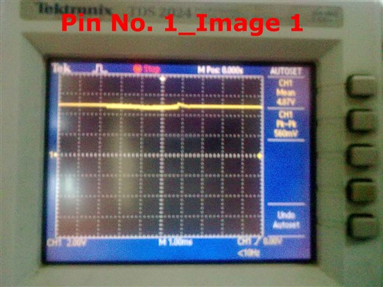
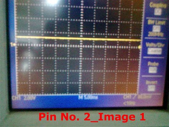
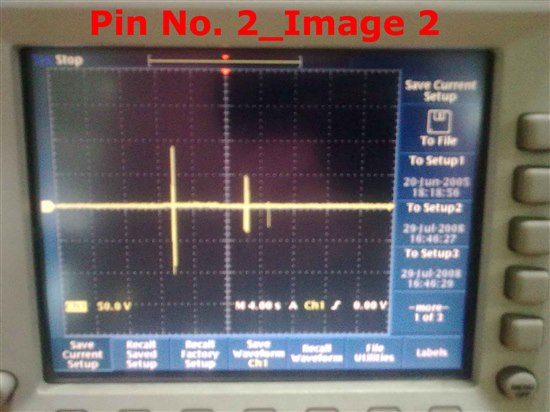
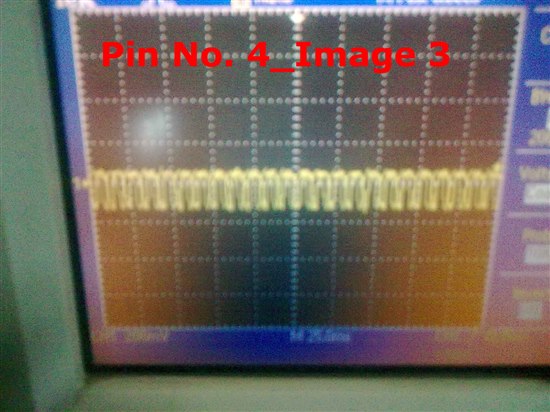
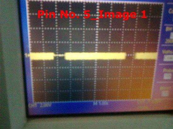
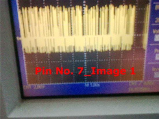
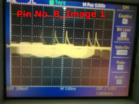
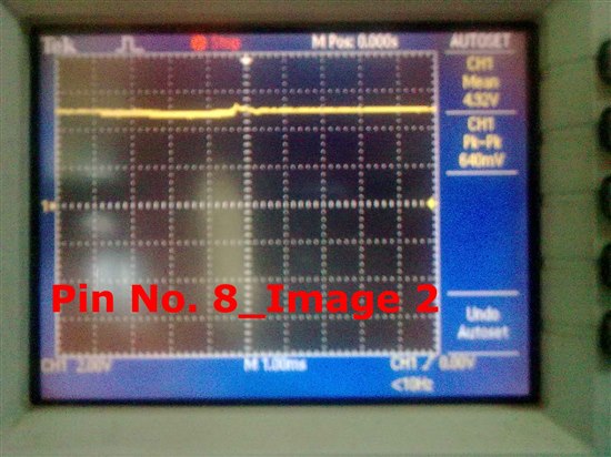
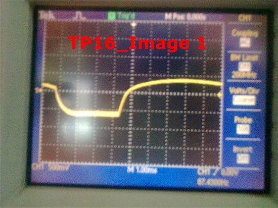
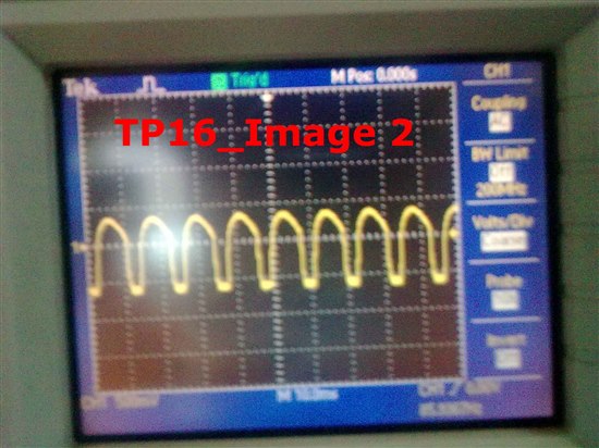
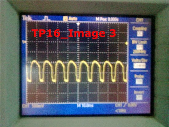
  • The schematic is identical to figure 15 in the datasheet and so should be okay.  I cannot see the inductor part number but I see that it is in a 1210 package?  Such a small packaged, 10uH inductor having a 1.5A current rating is rare.  What is the inductor part number? Can you send some measurements, such as the voltage at pin 2 and 3 and a scope shot pin 7, pin 8 and TP16?


  • Can you post your board layout?

    The board layout is very important and the IC may not work with non-optimal layout.  It will likely not work on standard breadboards that only take through-hole components as the extra lead length has inductance that can cause mis-operation.  The datasheet says: "The TPS6735 should not be used with IC sockets, wire-wrap prototype boards, or other constructions that are susceptible to noise pick-up."

    There is an EVM for the TPS6735 here: http://focus.ti.com/docs/toolsw/folders/print/tps6735evm.html You can order it and see if you get the same result.

  •  

    Inductor used :- Wurth Electronics Inductor with part no.- 744053100 (10UH,1.5A, SMD)

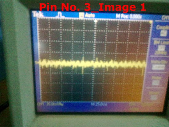
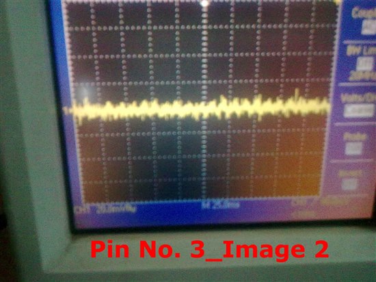
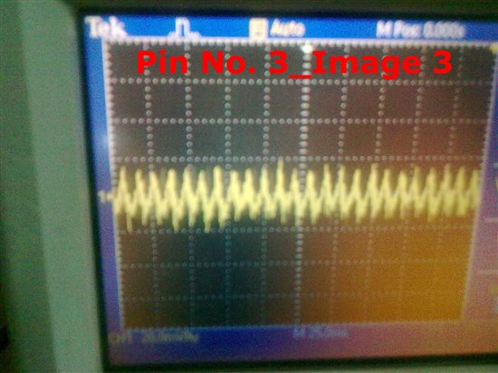
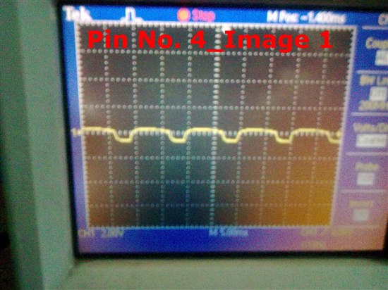
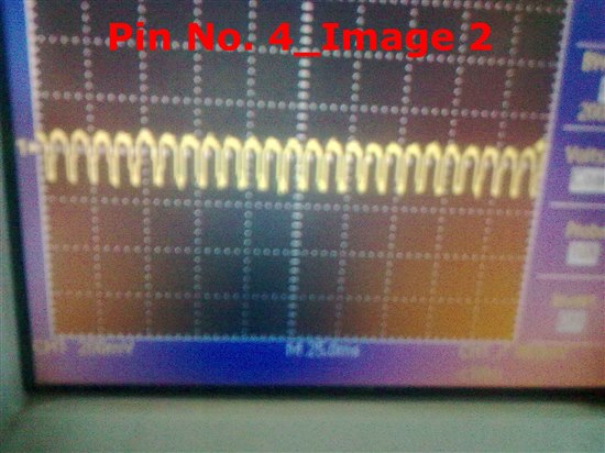
    Also the scope shots are given below


    So these are the Scope Shots for various pins. Also at TP16 we are getting only -1.24V output voltage instead of -5V. Kindly revert back ASAP.

  • Hii Chris


    We are not using the circuit on Bread Board or Wire Wrap Prototype Board. We have designed a board  and but as desired Output is not coming so we are parallely checking the circuit on bread board. Also one more thing if we connect the FB pin after diode means on Anode side of the diode that time desired output is not coming. Its giving only -1.24V. Also TPS6735 is heating alot. But if we connect the FB pin  before diode i.e. on Cathode side of the diode. That time output is coming -4.5V to -4.7V.   Also TPS6735 is not heating also. But we don't know why its showing such a characterstics as in Datasheet and reference schematics FB pin is connected after Diode only i.e.on Anode side of the diode.

    We have verified the Board layout and its perfectly implemented. Also kindly go through the  scope shots for various pins in the latest post.


    Thanks & Regards,

    Nishant

  • Yes, the output must be connected to the anode of the diode.  Make sure the diode is installed with the correct polarity.

    Does this occur on just one board or on all boards?  Can you test a new IC and see if it behaves the same?

    Do you have any load attached to the output?  If so, remove it and retest.

    Could you please post your board layout?  There is a lot of noise on your SS pin and it is at a low level.  This will cause the IC to not start.  Possibly noise is coupling into this pin from an adjacent noise source or poor grounding.  You can also remove R1 and R2 and retest.

  • The polarity of the diode is correct. It happens for all the boards.

    When we mount the Inductor then the IC is heating to much but after removing the inductor its not heating. But in both the cases we are not getting the desired output.

    We have tested with the new IC also.

    We have removed the laod also and tested. No change.


    Also we have removed the R1, R2 and C6 and checked. Still no change. Sometimes the Output gives -0.5V, sometimes -0.6 V and some times -1.24 V. And if we use typical circuit of the datasheet i.e. Figure 1 then it is giving -2.5V. And Also if we change the FB connection to the cathode side of the diode then it gives the -4.8V output. I have tried all possible ways. Kindly suggest some more points which we can try in our schematics. Can you send me any working board schematics.


  • Without the inductor, there should be no output.  The inductor and diode need to be present for the circuit to regulate and the FB pin needs to be connected to the output voltage.  Other configurations will not work.

    Since your circuit is the same as the schematic in the datasheet, the only possibility is layout or test setup.  The circuits in the datasheet have been tested and do work.  So, I believe the next thing to check is your layout.  You can order the EVM and evaluate it or post your layout.