Other Parts Discussed in Thread: PMP20220
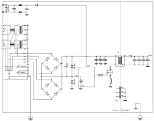
I have a PD SMPS design which uses the TPS23751 to power my application.
In addition to the PoE supply, i provide a DC input which is connected according Option 2 Oring (see datahseet Page 31 Figure 31).
Protection of the PD manager is based on SLUA736 for 2kV with additional 56V TVS diodes in parallel to the HOTSWAP-FET.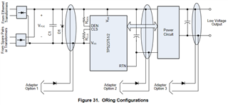
I do have a massive Surge problem.
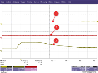
For the Test, the device is DC input powered with 24V
Ethernet is connected. PoE is not provided.
surge is applied common mode referred to PE. Only currents through the pim/sec capacitors (3nF) occur and with a rather low value (up to 3A)
While applying already a 500V surge pulse (1,2µs / 50µs) the PD manager switches off and remains off.
In this latched state, V.C is still 13V and V.B is still 5V. As both voltages are within valid range, the internal CONV.ON signal (see block diagram) should enable the converter.
... BUT it obviously does not work.
Beside powercycling I can bring the converter back to live by increasing the DC input voltage to above approx 38V.
I can only find one voltage in the datasheet which is in that area and would explain the behaviour. the PoE UVLO.
The question now is, when i operate the device with DC without any PoE PSE connected, why does the PD manager trigger the PoE UVLO and how do i avoid this ?
As the PoE Block diagram notes, that al voltages (incl. PoE UVLO) are referred to V.SS i would assume, that a small capacitor between V.SS and RTN might be an option, but i am not sure if this is possible with respect to the IEEE802.3
btw.: It is an 8 Layer design with massive GND plane underneath the PD-Mgr. VB and VC are buffered with 1µF ceramic caps directly beside their corresponding pins.