This thread has been locked.

If you have a related question, please click the "Ask a related question" button in the top right corner. The newly created question will be automatically linked to this question.

BQ76940: What is the difference among C0 and BAT- and GND_B from TIDA-01093?

Part Number: BQ76940
Other Parts Discussed in Thread: TIDA-01093

Dear,

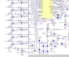
I had refered TIDA-01093 and designed circuit with bq76940 but used stm32F103. I am so curious about ground level among C0 and BAT- and GND_B?

I think C0 is same as BAT-. But C0 and GND_B have about 7V difference. Is it correct?

And what is the BAT pin function? If I measure 42V between C0 and BAT pin, BAT_HI and BAT_LOW value should be same as 42V?

Best regards,


3617.bms.pdf

  • I also measured cell voltage with multimeter from C0 to C13. All of value between each cell are amost 3.2V. but reading cell value with I2C interface is difference. 

    If I measre the value between VC0 and VC1, the reading cell value should be same as I measured. Am I right?

  • What is the purpose to seperate the GND as I asked? Is it possible connect all(C0, BAT-, GND_B)?

  • Hi David,

    C0, BAT-, and GND_B are all the same voltage. If you look at Page 4 of the TIDA-01093 schematic, you will see they are all connected at a single point. This is a typical single-point grounding scheme. I do not see these connections in your schematic, so this might be why you are seeing a voltage difference.

    I notice that you are using 10uF capacitors on VC0 and VC1, while you are using 1uF capacitors on all of the other VCx pins. It also looks like the power filter components are missing from your power pins (BAT, VC10X, VC5X). I recommend taking a look at this video to make sure you are following all of the recommendations: https://training.ti.com/how-create-schematic-bq76920-bq76930-and-bq76940 

    Best regards,

    Matt