This thread has been locked.

If you have a related question, please click the "Ask a related question" button in the top right corner. The newly created question will be automatically linked to this question.

TPS62420: Feed Forward Capacitor.

Part Number: TPS62420

Hello

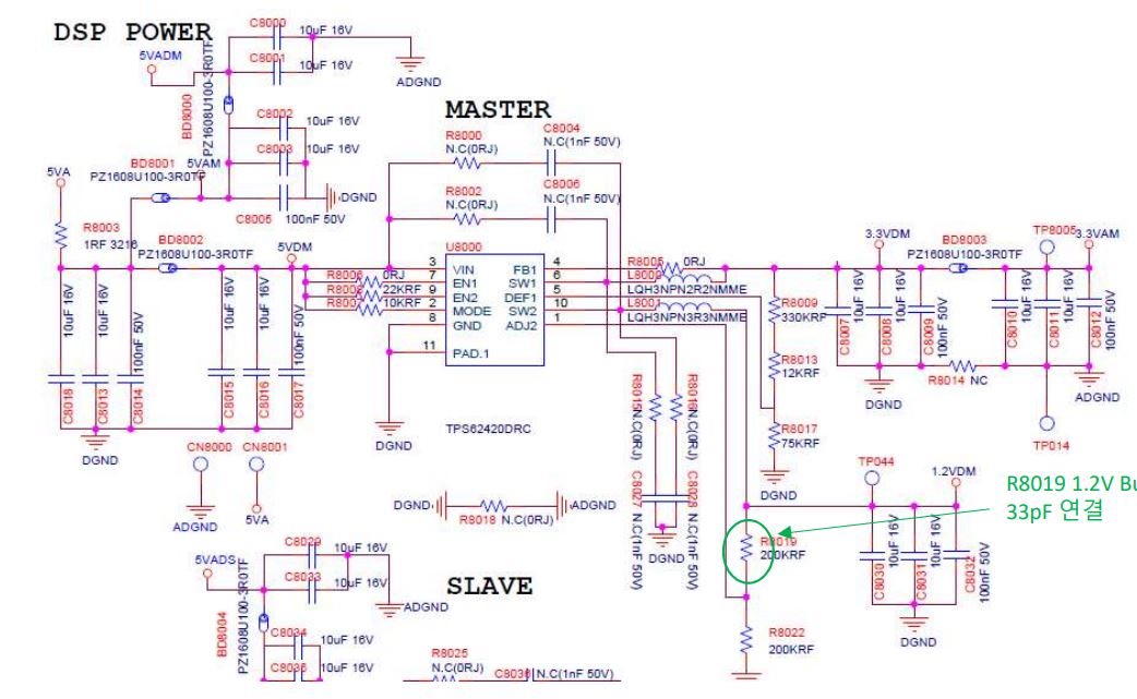
If I remove Cff, will it affect SW1 as well? 

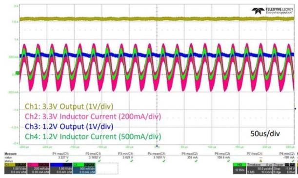
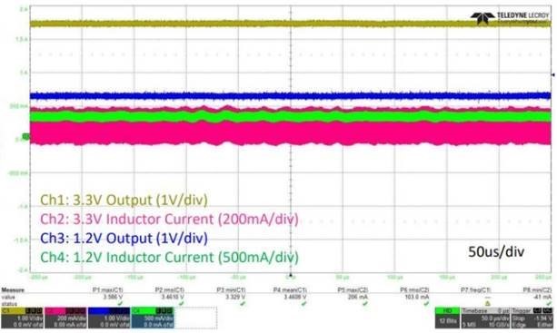
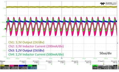
The waveform on the left is when Cff is removed, and the waveform on the right is when it is mounted.
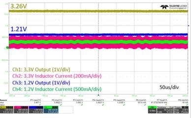
SW1 : 3.3V

SW2 : 1.2V

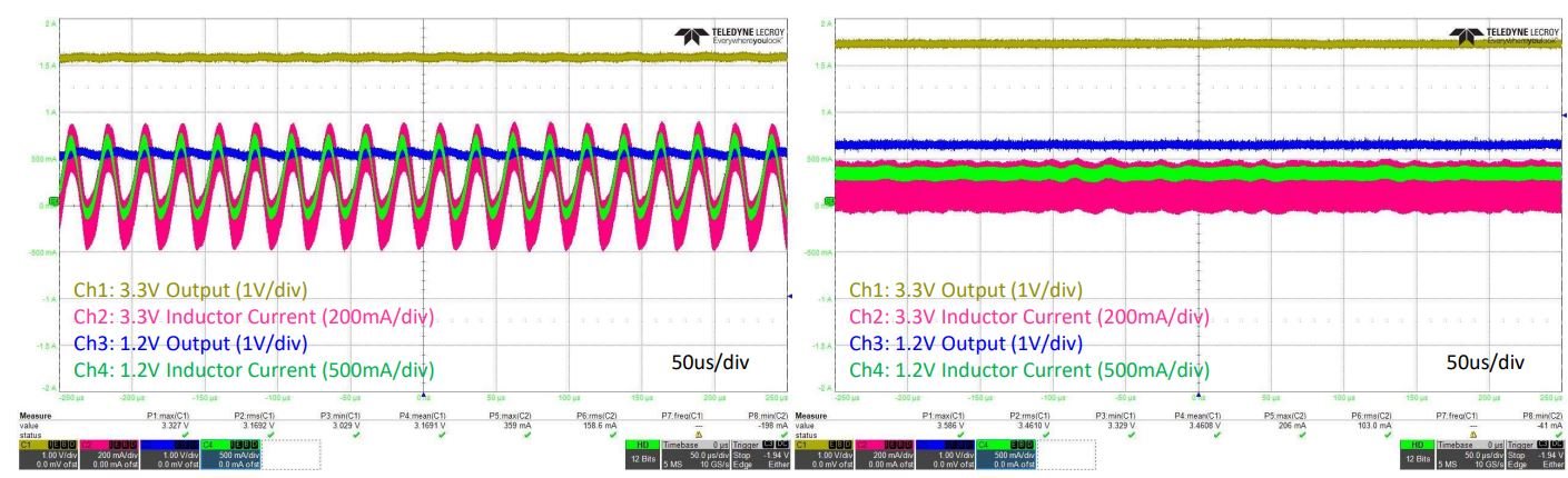
Can oscillation occur in SW1 by removing Cff?

Best Regards.

  • Hi,

    Kindly share the schematic for further review.

    Regards,

    Febin

  • HI Febin

    I have attached the schematic.

    Best regards

    Louis

  • Hi Louis,

    I reviewed the schematic and everything looks good.

    Converter 1 has an internal feedforward capacitor and therefore; there is no need for an external feed-forward capacitor. However, for converter 2, in addition to the internal feedforward capacitor, a 33-pF external feed-forward capacitor must be used for good load transient response. 

    A feedforward capacitor adds a zero and a pole to the control loop, which can be strategically placed to improve the phase margin (stability) and bandwidth of a power supply. It plays a major role especially for internally compensated dc-dc converters.

    Let me share some App notes that will be helpful for you.

    https://www.ti.com/lit/an/slva289b/slva289b.pdf?

    https://www.ti.com/lit/an/slva466a/slva466a.pdf?

    I hope this helps.

    Regards,

    Febin

  • Hi Febin

    We understand that adding a capacitor in the control loop can improve the transient performance.


    Also, we’re aware that the converter 1 in the IC has the internal capacitor in the control loop and the converter 2 does not, which a cap might need to be added if necessary.


    the above experimental result shows the current oscillations in both the converter 1 (the 3.3V one) and the converter 2 (the 1.2V one),

    which is tested without a capacitor in the control loop of the converter 2


    the other test result above is experimented with a capacitor in the converter 2 control loop.


    It cleary denotes that the converter 1 (the 3.3V one) inductor current has got stable even though we added a capacitor in the converter 2 control loop


    In the datasheet, it does not depict any cotnrol corelation between the two.


    We’d appericiate if you explain this in details.


    Regards,

  • Hi Louis,

    Febin is unfortunately on sick leave today. I expect that she will be getting back to you by mid of the week. Please let me know in case this is an issue for you.

    Thanks

    Yann

  • Hi Louis,

    I understand your question. However, I need to double check the design with the respective designer as this is a pretty old device. 

    I am OoO this week. Could you please wait until early next week? If not, we can assign someone from the team to support you.

    Regards,

    Febin

  • Hi Febin

    I'll wait to your answer until next week. 

    Best regards

  • Hi, Febin


    We have one more question for the IC design.


    We have large output capacitance, which is around 75-uF for each converter (Converter 1 and Converter 2).


    Since the datasheet says that the suggested output capacitance is 10-uF ~ 22-uF, our output capacitance might be quite large.


    However, our targeted application is an MCU power so we do want to have tightly regulated voltage (the reason why we use large output capacitance)


    Our 1.2V converter (Converter 2) control loop resistors are 200kohm / 200kohm which are within the suggested value (In the datasheet, 180kohm – 360kohm are recommended)


    We think the current oscillation comes from the slow transient response due to the large output capacitance and the large feedback loop resistors because the feedback resistor value 180kohm 360khom is basically recommended when the output capacitance is 10uF – 22uF, which is a lot smaller than ours.

    When we decreased the resistor value from 200kohm / 200kohm to 30kohm / 30kohm, the current oscillations have been removed like the above results. (We didn’t add a capacitor in the control loop in the converter 2)

    Obviously, converter performance is affected by many factors including output capacitance and feedback resistor value.


    We kindly ask you to review our design if it’s really okay to change the feedback resistor value like this without a capacitor added in the control loop of the converter 2)

    Please refer to our schematics attached earlier as well.

    Regards.

  • Hi Louis,

    Please be informed that I am just back from my vacation. I will provide a feedback by mid of this week...

    Regards,

    Febin

  • Hi Louis,

    Let me first thank you for your patience and understanding.

    I think the actual problem for instability in both the converters is the very high output capacitance that you clearly identified. We cannot recommend and guarantee the performance of the device beyond datasheet specifications.

    The stability of the converter depends on several factors like the LC filter, resistive divider (for devices with internal Cff), external Cff, layout, etc.

    I understand that a large Cout is required on both rails due to the application requirements. In this case, what you can try is reducing the inductance (<2.2uH) to compensate for the large Cout. The LC product should remain almost constant to keep the regulator stable. I recommend to use higher feedback resistors itself. When the feedback resistors are much lower, then Cff do not play a role anymore. However, it shall be the customer's responsibility to test and verify that the performance of the device meets your requirements with a BOM beyond the datasheet recommendations.

    In TPS62420, both the converters are completely independent and they do not have a correlation. What you observe could be a result of a combination of several factors like the layout, parasitics, ESR of the capacitors. What is also important here is the positioning of these large output Caps on the board. If possible you could try placing them away from the TPS62420. 

    Regards,

    Febin

  • Additionally, I would like to inform you about our latest dual converter, TPS6244x the successor of TPS6242x.

    TPS6244x can have up to 200uF effective output capacitance and has a COMP/FSET pin to change the control loop compensation and frequency settings. Please consider them for newer designs. It is not however p2p compatible with TPS6242x.

    https://www.ti.com/lit/ds/symlink/tps62442.pdf?

    Regards,

    Febin

  • Hi Louis,

    Do you have further questions?

    Regards,

    Febin

  • Hi Febin

    This issue has been resolved

    Thanks.

    Best regards