This thread has been locked.

If you have a related question, please click the "Ask a related question" button in the top right corner. The newly created question will be automatically linked to this question.

LM25037: LM25037 duty cycle problem [ emergency]

Part Number: LM25037

I designed electric schematic diagram than input voltage is 40~55V ,and output voltage is  24V ,schematic as figure below:
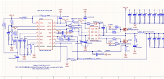
The problem is that output voltage is unstable , and  LM25037's OUTA &OUTB PIN output the maximal duty cycle is 50%, it cannot be set by RT2 resistance,
Question: Is it that LM25037's OUTA &OUTB PIN output duty cycle maximal 50%?   if not is what limit this dury cycle except RT2 resistance?

  • Section 7.4.5 of the datasheet says the maximum duty cycle of OUTA and OUTB are inherently limited to less than 50% and is based on the value of the RT2 resistor.

    Based on your schematic:  For RT2=41.2k I calculate dead-time, DT=206ns.  For RT1=15k I calculate Fosc=379.4kHz.

    I can solve Equation 1 in the datasheet for Dmax = 92.18%.  This is the duty cyle of OUT1 + OUT2.  So ~46% from each OUTx.

    Is this schematic implementing a buck regulator.  I'm not sure the LM25037 can do this.

    Regards,

    Eric

  • Hi Eric

    Thank's for your reply.

    1. The maximal duty cycle of OUT1 is less than  50% respectively, is it right? 

    2. If OUT1 is less than  50% so that my design cannot be implement .

  • Hi Jianlin,

    1) Yes. OUT1 (and OUT2) maximum duty cycle is less than 50%.  Section 7.4.5 of the datasheet says this.

    2) Unfortunately, your design needs a (minimum) duty cycle of Vout/Vin, 24V/48V = 50%, higher considering losses.  The LM25037 does not specify synchronous buck in its applications.  It's meant to be used for  "Full-Bridge, Half-Bridge, Push-Pull" topologies.

    OUT1 and OUT2 alternate with each having the same on time.  The typical Push-Pull topology is shown here.

    Eric