Other Parts Discussed in Thread: BQ24616, BQ24130
Hello,
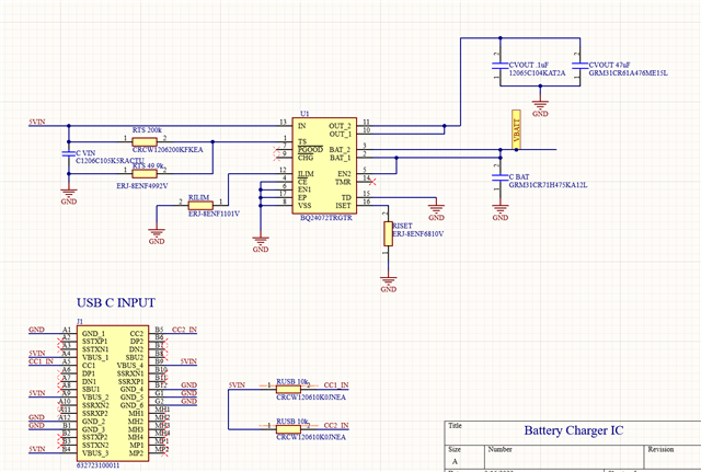
I want to use the BQ24072TRGTR Battery Charger IC to charge my LIPO battery 3.7V 6000mAh. I solely would like to supply power to my loads through the battery. Will not be using TS function.
This thread has been locked.
If you have a related question, please click the "Ask a related question" button in the top right corner. The newly created question will be automatically linked to this question.
Hi Andres,
Welcome to E2E!
The BQ24072T can only charge at max with 1A current. With a 6000 mAh battery, this may cause a safety timer fault (which based on your schematic, is set to default 5 hours with TMR floating). If you are connecting your load to the battery, this may cause issues with battery termination (and so also a safety timer fault). It is probably better to look at non power path switch mode chargers such as the BQ24616 or BQ24130. To counteract the latter symptom, it's recommended to connect the load to the OUT pin. If there is no input voltage at the IN pin, the device will power the OUT pin with the battery.
If you do decide on using the BQ24072T with the warnings I've mentioned, this is fine. I would recommend pulling the EN2 pin to OUT or IN.
Best Regards,
Anthony Pham
Hi Anthony,
Thank you so much for replying. On the datasheet, I read that it can charge at a max of 1.5A. Am i reading that correctly? There is currently no non power path chargers in stock but I was able to get my hands on this IC. Would I still be able to bypass the OUT without running into any issues? My idea is that I would not want to supply power to my loads(boost converter to then supply power to a MCU). using the OUT pin. The input voltage in the IN pin would be 5V coming from the usb type c port. My intent for this IC is to solely charge the battery safely and supply power to loads using the battery. Sorry for repetition.
Thanks,
Andres
Hi Andres,
Yes, if there is no load and the input current & voltage is sufficient for 1.5A charging, it will charge at 1.5A.
Would I still be able to bypass the OUT without running into any issues?
Yes, this is fine.
My idea is that I would not want to supply power to my loads(boost converter to then supply power to a MCU). using the OUT pin
Is there a particular reason why? Will these loads be active all the time? As mentioned before, if the BAT pin is pulling current to charge your battery and the connected loads, your battery will not be charged completely as there's no way to monitor current going only into the battery to complete a proper charge cycle.
Best Regards,
Anthony Pham
Hi Anthony,
Great question, my intent was to find a switch method, possibly a mosfet or so, in order to prevent the battery from supplying power to loads while charging. I have a project to supply power to a wearable device that will have the battery, pcb, and mcu inside a casing. So the scope of the power system is that when a AC/DC adapter is supplying 5V to the IN pin via usb, the Battery Charger IC would only charge the battery(A fuel gauge would monitor the battery) and no loads(Boost Converter, MCU) will draw current from the battery. The device would be "OFF"(As in MCU will be off) while charging. Does this sound reasonable? Any feedback is greatly appreciated thank you.
Thanks,
Andres Perez
Hi Andres,
I see, that sounds fine. As long as loads connected to the battery are off when charging, I think that should minimize any issues I see regarding application.
Regarding the schematic:
I would recommend pulling the EN2 pin to OUT or IN.
I wouldn't expect any issues if your battery is within the logic high level for EN2 but if you aren't using OUT, it may be easier that way. There can be different waveforms on BAT if a battery isn't connected and if your battery falls too low this can affect the voltage seen by the EN2 pin.
Other than that, it looks good. Let me know if there are any more questions. Feel free to return to E2E if there are any more questions and best of luck on the project!
Best Regards,
Anthony Pham