Because of the Thanksgiving holiday in the U.S., TI E2E™ design support forum responses may be delayed from November 25 through December 2. Thank you for your patience.

This thread has been locked.

If you have a related question, please click the "Ask a related question" button in the top right corner. The newly created question will be automatically linked to this question.

UCC21530-Q1: measurement for propagation delay

Part Number: UCC21530-Q1
Other Parts Discussed in Thread: UCC21530

Hi Expert,

My customer tried to measure the propagation delay time from INx to OUTx as below table from datasheet. Their result seem unreasonable, 120ns as they said. So I would like to ask the right way to measure the propagation delay time.

  1.  For the measure point, to avoid the extra delay time caused by RC network, I think we should choose c, d and refer to the AGND, e, f and refer to the VSSA and VSSB
  2.  The probe should be placed as close as these pins.

Please add some comments for the measurement procedure of propagation delay time.

Besides, could you please share the waveform you measured for UCC21530 propagation delay time? You can share through the email. 
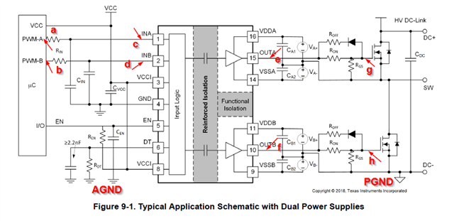
Thanks!
Ethan Wen

  • Hi Ethan,

    Thanks for reaching out on E2E!

    Yes, I agree with your assessment of the probe locations/methods.

    Another important element will be where to measure along the waveforms. For example, T_PDHL should be measured from the input low threshold voltage (1V typ.) to the falling output (90% of max. value). The input thresholds are given in section 6.9 of the datasheet. Figure 7-4 in datasheet, though intended to explain dead time, also provides a visual for the propagation delay measurements. Additionally, this training video explains this starting at around 0:53.

    If the customer still has trouble, please follow up and we can look at their measurements in more detail.

    Best,

    Olivia Brandel