This thread has been locked.

If you have a related question, please click the "Ask a related question" button in the top right corner. The newly created question will be automatically linked to this question.

LM3488: LM3488: I am trying to use a SEPIC/CUK combination to create +80V and -80V (the one reported in TIDA-010057) but am getting no output and Inductor is getting very hot.

Part Number: LM3488
Other Parts Discussed in Thread: TIDA-010057,

Hi We have manufactured the TIDA-010057 PCB and have started testing.

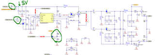
The only portion of the circuit we are having trouble with is the LM3488 HV Section.

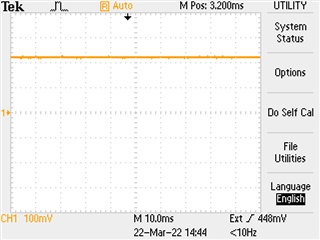
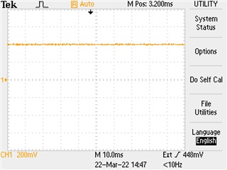
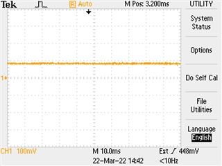
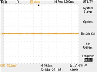
We are not getting outputs on the HVP and HVM Rails in the order of milli Volts.

Also Inductor L1 is getting extremely hot.

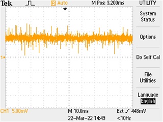
Getting no oscillating signal out on Pin 6 (DR) Signal of the LM3488.

ANy advise where to start looking would be highly appreciated.

  • Hi Charl,

    Sorry to hear and thank you for designing with the LM3488.  Could we get some clarifications which may help us in debugging?

    • Did you build the PCB per the original TIDA-010057 design published by TI, like using the existing Gerber files, or you re-captured the schematic and re-designed PCB?
      • If you recaptured the schematic and redid the PCB, could you share your own version of the schematic?
    • Did you use the exact BOM of the original TIDA-010057 from TI, or you modified the BOM?
      • If there are some differences, could you share those discrepancies?
    • Were the operating conditions within the recommended conditions of TIDA-010057?  
      • If the conditions are different, could you specify?

    Regarding the LM3488 itself, it sounds very strange that strange that your L1 got really hot but there was no signal at DR pin.  Please check if Q1, C25 and C35 are shorted.  Otherwise there would be no path for current to flow through L1 and not heating in L1. 

    Could also you monitor the following signal and share the scope pictures?

    • COMP, FB, VIN and ISNS?
    • Pleas also monitor FA/SYNC/SD and DR pin

    Thanks,

    Youhao 

  • Hi Youhao,

    Thank you for your response.

    Yes we have manufactured the TIDA-010057 using the Gerber files and exact same BOM provided by TI.

    We are currently testing the TIDA-010057 by powering it from USB port on Laptop and no other PCB plugged into it.

    We tested and we do get short between Q1, C25 and C35.

    I have attached the scope measurements from all the LM3488 pins.

    COMP:

    COMP

    DR:

    DR

    FA:

    FA

    FB:

    FB

    ISEN:

    ISEN

    VIN:

    VIN

  • Hi Charl,

    Thanks for the information and screenshots. We will discuss this internally and come back to you within the next few days.

    Regards,

    Harry

  • Thanks Harry,

    Regards.

  • Hi Charl,

    Your scope shots are not what we expected from a good IC.  It seems the IC is already damaged.  Could you replace the IC with a new and redo the test?  Please take necessary steps to prevent possible ESD destruction to the IC during handling.

    I am also checking with the TIDA-010057 designer for the test report.  

    Thanks,

    Youhao

  • Hi Youhao,

    Thanks for your feedback.

    Any ideas of what could have caused the IC to be damaged besides ESD?

    We have only powered the TIDA-010057 from USB on Laptop thus far.

  • Hi Charl,

    I am Abhishek and I have worked on this design.

    Do you mean that replacing the IC worked and you are getting the required voltage? 

    If it isn't, I looked at the previous conversation and I think in order to figure out the issue, we can start with isolating the rest of the board with the HV circuit. 

    From the schematic shown below, can you ensure that the following red crossed DNP components are indeed unmounted.

    1. Input supply Isolation: Remove R54 0 ohm and directly give 5V from external supply on input caps C22-C23. Also remove C28 marked in green to keep the IC frequency decided by R39

    2. For start may be you can reduce the output voltage to say 30V - 40V l . You can do that by reducing the R42/R45 ratio, which follows the following relation with output voltage

    Vo = (1+R42/R45) x 1.26 V

    3. Ensure that there is no short in the circuit :between input supply and gnd; between output voltage and gnd (both positive and negative).

    Let me know if you are able to bring up till this point.

    Thanks & regards,

    Abhishek

  • Hi Abhishek,

    Thanks for your feedback. I have not yet replaced the IC.

    I will replace the LM3488 with a new one and follow your guidelines for testing this circuit in isolation.

    I will let you know the outcome.

    Regards,

    Charl Peters.

  • Hi Charl,

    Thanks for doing the experiments.

    Are you able to make any progress, let me know if you are need any assistance.

    You can send me a mail as well on abhishek.vishwa27@ti.com

    Thanks & regards,

    Abhishek

  • Hi Abhisek,

    I have now replaced the IC and retested following your guidlines but am getting exactly the same outputs as per my previous screenshots.

  • Hi Charl,

    I'm sorry to hear about the same. 

    There must be something grossly wrong, did you check for any shorts on the high voltage circuit?

    Can you check if the FET is good? 

    Regards,

    Abhishek

  • As we have not heard back for more than a month now, I am closing this thread.