This thread has been locked.

If you have a related question, please click the "Ask a related question" button in the top right corner. The newly created question will be automatically linked to this question.

LM7480-Q1: LM7480 implementation

Part Number: LM7480-Q1
Other Parts Discussed in Thread: LM7480, , TPS2411, UCD3138, LM74700-Q1

Hello,

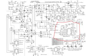
I wanted to replace TPS2411 (support max 16.5V) used as oring controller in UCD3138PSFBEVM shown in the below attached screenshot. I have higher voltage application (requirement of 48V) so wanted to use LM7480 ( support max 65V). I Have gone through the datasheet of LM7480-Q1 which looks quite different as compared to TPS2411, So, needed your guidance in replacing the old controller with the new one without creating much difference in the pre existing schematic.

 Thanks and Regards.

  • Hi Priya,

    Thanks for reaching out to us. Can you please help answer the following questions ,

    1. What is the Max input voltage (both DC and transient) seen by the ORing controller in your application ?
    2. Is reverse current blocking (for ORing application) the only key feature required for your system ? 
    3. TPS2411 has few features that LM7480x-Q1 do not have, like programmable reverse current threshold, Fault indication, Power Good indicator. If these features are not required, you can replace TPS2411 with  LM7480x-Q1.
    4. What is your end application ?
  • Hello,

    Basically I am designing DC-DC converter (400V input to 48V output at a power level of 2.5kW ) using UCD3138 with the help of EVM module (400V to 12V at a power level of 600W) available. I have made chances accordingly in the base board (that should work ) but got stuck in the oring controller part. 

    1.  Typical voltage received : 48V . Maximum voltage received : 56Vdc . ( not very sure about transient).

    2.  ORing application is not the only key feature required, but is a important part of the system.

    3. Those features can be skipped for now in order to implement this, but if you have any other controller suggestion for my requirement including these features then we can go with that as well. (just want to retain other part of the schematic unhanged to the maximum extent possible).

    4. DC-DC converter (explained above).

    Thanks and Regards.

  • Hi Priya,

    For 56V DC ORing application, the best options we have are LM74700-Q1 and LM7480-Q1.

    1. LM74700-Q1  is capable of handling 60V DC and 65V transients at its input. This device can drive Ideal Diode FET which can block reverse current required for ORing application. As you can see in the circuit below, there are only few components that you need to select - FET,  Charge Pump Cap and input TVS (to protect from Transient input voltages > 65V).

    2. LM7480-Q1 is capable of handling 65V DC and 70V transients at its input. This device can drive both Ideal Diode FET and load switch FET (for forward current blocking) and hence offers additional features like over voltage protection. 

    LM7480-Q1 can also be used in a simple Ideal Diode configuration if additional protection features are not required. 

    Once you choose the appropriate controller, you can refer to the ' Application and Implementation' section in the datasheet for guidance on component selection. You can share the schematics once they are ready for review. 

  • Hello,

    For simplicity I want to use LM74700-Q1 as my oring controller in place of TPS2411. Kindly let me know the suitable TVS diode based on my requirement mentioned above.

    And regarding other connections with respect to UCD3138PSFBEVM schematic, kindly verify the below attached schematic and let me know the required changes.

    Thanks and Regards,

    Priya

  • Hi Priya,

    What is the FET Part Number that you have selected ? The FET used in the schematics is only 20V rated. For 56V max DC input, you can consider using a FET with around 80V rating.

    Select a TVS based on the guidelines below,

    1. The TVS breakdown voltage should be greater than the Max DC voltage applied at the input.
    2. The maximum clamping voltage of the TVS  during  transients at the input needs to be less than the Absolute Maximum rating of the IC. 

    In case, the TVS is selected based on point 1 but failed point 2 then you need to select a high power TVS. 

  • Hello,

    Currently I am using IRF60B217 MOSFET (60V rating). As per your suggestion I have looked for 80V rating FET ( TK7R0E08QM).

    1. So basically the TVS breakdown voltage should be greater than 56V?

    2. Maximum clamping voltage of TVS during transient at the input needs to be less than 65V?

    Also do let me know about the other connections in the screenshot attached above if they are ok. (EN will be shorted with anode as per datasheet application)

    Thanks and Regards

  • Hi Priya,

    Please see my response below,

    1. So basically the TVS breakdown voltage should be greater than 56V?

    • Yes

    2. Maximum clamping voltage of TVS during transient at the input needs to be less than 65V?

    • Yes, for LM74700-Q1, 65V being the Abs Max rating, the TVS selected should have a clamping voltage of < 65V during all the transient conditions occuring at input. 

    Also do let me know about the other connections in the screenshot attached above if they are ok. (EN will be shorted with anode as per datasheet application)

    • The remaining connections look OK to me.  
    • For 52A load current (2500W/48V) , how many TK7R0E08QM FETs in parallel are you planning to use (considering Max Ambient temp, RQJA, Rds(on), etc..) ?
  • Hello Praveen,

    I wanted to know if TVS is compulsory, as I am not able to find the suitable TVS as per the conditions mentioned above.

    Also the FET (TK7R0E08QM) has 64A current capability and low power dissipation, so I am planning to use two in parallel to be on safer side. Do let me know if you have any suggestions.

    Thanks and Regards.

  • Hi Priya,

    You cannot get away with TVS unless you are sure that the input transient max voltage is less than 65V. One advantage you have here is that there is a good amount of Capacitance (22uF) at the input. This should be good enough to suppress voltage transients. But, I would recommend to at least have a place holder for TVS in your initial design and test it in all conditions to verify the max voltage appearing  at input  of LM74700-Q1 in all conditions. 

    Regrading the FET Rds(on) selection, you need to check the I2R losses in the FET and check the temperature rise of the FET junction. As rule of thumb we generally allow the max junction temp. of the FET to be < 100C. For these calculations, you need to work with FET Rds(on), RQJA (FET thermal resistance) which also depends on Layout, Max ambient temperature in your system.

  • Hello,

    I have seen two TVS options as per the specifications discussed above. Kindly let me know which one to go with:

    1. SMCJE8-5CA : breakdown voltage (min)- 94.4V ; clamping voltage (max): 14.4V ; Power pear pulse - 1.5kW ; current peak pulse- 11A ; bidirectional.

    2. XGD10402KR : breakdown voltage (min)- 250V ; clamping voltage (max): 40V ;  bidirectional.

    Thanks and Regards

  • Hi Priya,

    The breakdown voltage (VBR) of the TVS will be always lower than the clamping voltage. Only after the TVS breaksdown, it will start clamping to a certain voltage level depending on the current flowing through it. The current flowing in the TVS will depend on the transient voltage and its impedance. 

    The breakdown voltage of SMCJE8-5CA is 9.44 (not 94.4V). As the breakdown voltage of the TVS has to be greater than the MAX DC voltage (56V), this TVS is not suitable. 

    XGD10402KR is an ESD diode and not TVS. ESD diodes are similar to TVS diodes but are of lower power rating. These devices are generally only rated to pass low energy transient pulses like IEC 61000-4-2. So, this diode is also not suitable for this application.

    You can consider using SMCJ51A. This diode has a minimum  VBR of 56.7V. The max clamping voltage shows as 82.4 V but this is at a peak pulse current of 18.2A flowing through it. The clamping voltage will be less than 65V for lower current flowing through the TVS. **Like I said earlier, to know the exact clamping voltage, you need to know the transient voltage and its impedance.