This thread has been locked.

If you have a related question, please click the "Ask a related question" button in the top right corner. The newly created question will be automatically linked to this question.

LMR50410: Inductor DCR

Part Number: LMR50410


Hi 

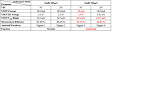
The customer replaces two inductors with the same inductance (10uH) and different DCR (105mΩ/ 520mΩ) on the EVM to simulate the situation we want to apply (VIN=9V/20V; VOUT=3.3V; IOUT=183mA), The results show that the two inductors are different, as described in the following chart and text:

1. Does LMR50410XDBVR have requirements for the DCR of the inductor?

2. Why does a higher inductance DCR make the LMR50410XDBVR function abnormally?

  • Hello

    Any switching regulator will malfunction if the inductor resistance is too high. 

    First, a high resistance will reduce the efficiency.

    Second, high resistance will reduce the time constant of the inductor, compared to the switching period; L/R.

    This will result in a non-linear current waveform, possibly upsetting the current mode control architecture.

    The size of the inductor must be based on the high-side current limit of the device, in this case between 1.6A and 2A.

    Sizing in this way will usually result in an inductor with low enough resistance to provide a large time constant compared to

    the switching period.

    In your case I would use a 10uH inductor with a resistance of 100mOhms or less.

    If you monitor the switch node and the inductor current and compare between the two inductors, you should notice a difference

    in the waveforms.

    Thanks