This thread has been locked.

If you have a related question, please click the "Ask a related question" button in the top right corner. The newly created question will be automatically linked to this question.

LM5170EVM-BIDIR: Bypass Current compensation - LM5170EVM

Part Number: LM5170EVM-BIDIR
Other Parts Discussed in Thread: LM5170

Hello,

Good afternoon

Hope you are doing well.

I would like to ask, if we can bypass the current loop compensation from LM5170 in the EVM. I wish to use only the power stage from the EVM.

Also, If bypassing is possible what can be the step to step instructions to follow.

Thank you

  • Hi Jeet,

    Thank you for posting but I am confused by your question.  What do you  really mean you just use the power stage of the EVM? 

    Also note that the LM5170 is an average current mode controlled device. If you do not use the current loop compensation, you will lose the benefits and also the performance presented in the datasheet and user's guide. For instance, you may not achieve balanced power sharing between the two channels. 

    Please share more details about your particular application so we can understand, and support accordingly.

    Thanks,

    Youhao 

  • Hello Youhao,

    Thank you for responding.

    I will be using LM5170EVM as a power optimizer for transferring power from PV panel to resistive load. My end application would be to use LM5170EVM as a boost converter for light load conditions in PV panel with 20 W output power.

    And based on the design, I will have to change the inductance to 10 uH and increase switching frequency to 250 kHz. Is it advisable to do so?

    Also, from above discussion it seems that there is no way we can bypass inner current loop compensation from the system. And so, I will be utilizing the inner current loop.

  • Hi Jeet,

    Yes you can increase the inductor and frequency.   

    Thanks,

    Youhao

  • Thank you for instant response.

    if there any limitations for changing value of inductances and frequency?

    Thank you

  • Hi Jeet,

    There is not particular limitations for these parameters as long as they are within the datasheet recommended range.  For instance: frequency should be between 50 to 500kHz.  The inductor should have a ripple current not great than 80% at full load.  Once you change the EVM parts, please re-run the design calculator to adjust the loop compensation in accordance.

    https://www.ti.com/lit/zip/snvc205

    Thanks,

    Youhao

  • Hello,

    I tired changing the switching frequency of gate signals from 100 kHz to 155 kHz, by changing the R1 and R5 resistors from 95.3 kohms to 61.9 kohms. But when I test the switching frequency on EVM, I am still able to see 100 kHz switching frequency at the gate signal.

    Is there any further changes required to increase the switching frequency?

    Test operating condition:

    Input voltage: 15 V

    output voltage: 50.5 V

    Boost operation

    Load resistor: 2000 ohms

  • Hi Jeet, 

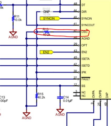
    Please note that the oscillator programming resistor is R13 on the EVM.  Yes you should also adjust R1 and R5 in accordance.