Other Parts Discussed in Thread: BQSTUDIO
Apologies if these should have been posted as individual posts but I couldn't access the forum through the weekend and the questions piled up.
We have the BQ76952 on a few of our 6S battery packs. The intent is to run semi-autonomous, but in the short term to get samples out the door I will let them operate fully autonomously. I have a few issues that I need help with, but didn't want to collect the wrong data so please let me know what I need to get you for each question to get it resolved. I have NOT used the software, nor do I have any way to use the software with my IC in circuit.
A bit about our board:
- Most of our circuit (as you'll see below) is derived from the BQ76952 eval...which we didn't have time to actually test
- We aren't utilizing any analog temperature inputs
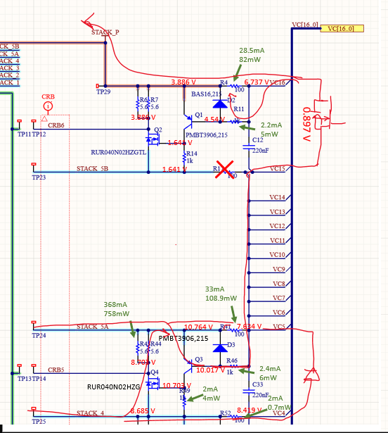
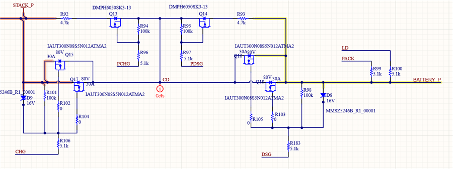
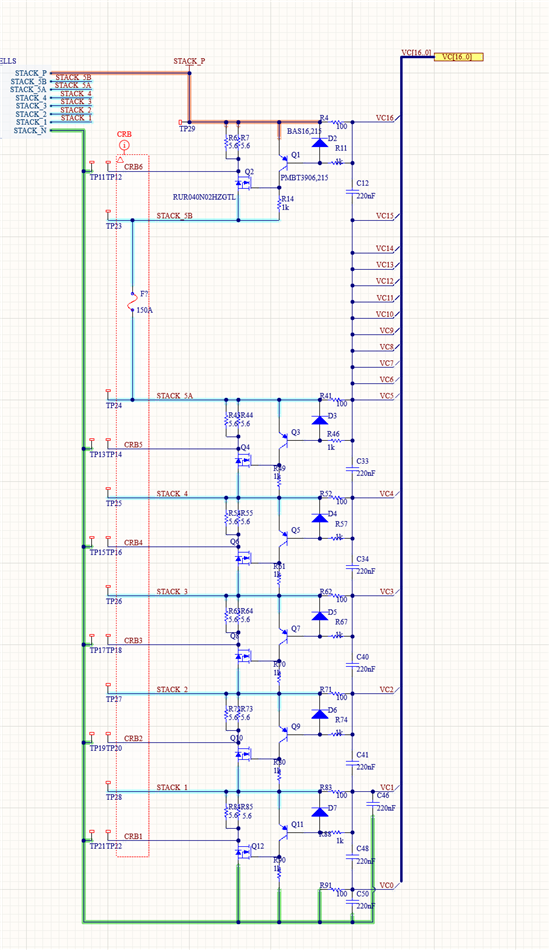
- Cell balancing is done with external nmos and pnp transistors...I believe this was pulled from another TI reference.
- I2C from host MCU
- Not using the fuse drive. We implemented an inline fuse between cells 5 and 6 due to physical constraints.
- Not using the AFE internal voltage regulators
- I have many board components powered from STACK_P
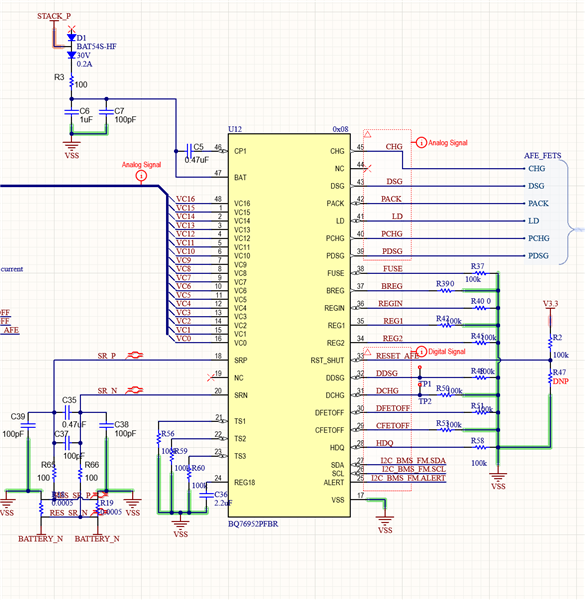
(RST_SHUT correction...R2 DNP, R47 100k)
Here is the startup sequence:
When the mcu comes online it resets the AFE by holding RST_SHUTDOWN high for ~1 second. Then it waits a few seconds before starting by polling alarm raw status to check for FULLSCAN on a two second interval.
Once complete I enter config mode, and load in values. I haven't used that software tool so my settings aren't compiled succinctly but here is what I have:
- Vcell mode: 0x801F (cells 1-5, and top cell 16...total 6 cells)
- CC gain: 0x41EF41F2 (cs resistor is 0.25 milliohm)
- Capacity gain: 0x4B081C6A
- Enabled protections A: COV, SCD, CUV, OCC
- DSG current threshold: 5000 mA
- CHG current threshold: 5000 mA
- Balancing
- configuration register: CB_RLX
- all temperatures left untouched
- interval untouched
- max cells left a 1 (though I did try 2 as well)
- min cell v dsg: 2180 mv
- delta relax: 15mv
- stop delta relax: 5mV
- CUV threshold: 42 (2.125V)
- CUV delay: 28
- CUV hysteresis: 1 (I see now it's supposed to be 2, but I would hope the AFE checks this? I'll update them now and see if anything changes)
- COV threshold: 52 (2.631V)
- COV delay: 28
- COV hysteresis: 1 (I see now it's supposed to be 2, but I would hope the AFE checks this? I'll update them now and see if anything changes)
- OCC threshold: 12
- OCC delay: 1
- SCD threshold: 2
- SCD delay: 1
- DCHG and pin config: 0x40
- ALERT pin config: 0x82
- CFETOFF and DFETOFF pin config: 0x02
- DA config: 0x19 (mV, and I set this to use the internal temperature sensor because I thought maybe it was preventing balancing from not having a source)
- power config: 0x39C0
- FET_EN done here...should it be within or outside config?
- exit config mode
Wait 4 seconds. Then start polling data.
I have three main questions/issues.
- I'm not measuring any balancing happening. I am checking CB_ACTIVE_CELLS and it does tell me cell 16 is balancing, but I'm not seeing anything on the board. And none of the cbstatus registers are incrementing. Our analog power engineer has not yet diagnosed the transistor network to see what is going on.
- Is there a maximum difference where balancing wont occur? I have two cells drastically out of balance I want balancing to bring up
- I'm seeing COV alerts but the voltage readings aren't at my configured limit. I have my COV threshold at 2.631V, but I'm seeing COV alerts at around 100 mV under.
- Does the value have to CROSS the threshold, or does it have to get within one bit (50.6 mV) of the value for the alert to trip?
- I'm pulling in COV, CUV, and all fault signals when the alert line is asserted. I would expect COV to show the value the instant the alert was thrown. Looking at the documentation again I see it says "records the cell voltage measurement made just after the latest COV event.
- What is "just after"? Is that on the normal loop interval...making the age of the snapshot value between 0 and 31.5 ms with FASTADC and LOOP_SLOW = 0?
- I'm not sure why I have FAST_ADC set, I'll see if there's a difference without it set
- With the fuse removed from our circuit, we still have a current path on the board. It seems like voltage is being drawn out of cell 4 and 5 to feed STACK_P and power the board.
- I have voltage measurements across all balancing components, again our analog engineer hasn't reviewed yet.
- Could you tell me if you see anything obvious, and anything I need to know about the power fets within the AFE that could be allowing enough current to flow through enough to power on the PNP at cell 4?
Please let me know what data, and in what format you would like to see to assist. Or if anything you see already stands out as obvious.