This thread has been locked.

If you have a related question, please click the "Ask a related question" button in the top right corner. The newly created question will be automatically linked to this question.

LMR62421: Not working without a series resistor at pin 4, (Enable pin)!

Part Number: LMR62421

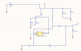
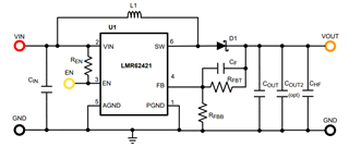
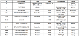
I am using LMR62421 as a boost regulator, Vin from 3.1V to 4.2V, Vout 12.0, 200mA. I have assembled 5 prototypes non were working up to place a 100K Ohm resistor in series with enable pin.(pin4).

The datasheet does not mention or imply that it is mandatory place a series resistor at pin 4, on the other hand, all application circuits in the datasheet, have it. 

I am wondering if it is really necessary? 

Thank you all.

Regards,

Elcio

  • Hi Elcio,

    it is ok to omit the resistor with EN pin, you can just connect the pin to Vin or controlled by GPIO. Hope the answer can help your concern.

    BRs,

    Eric Yue

  • Hello Eric,

    Thank you for your answer. 

    For some how when I do not have place the EN pin resistor, the regulator LMR62421 gets damage. I verified that it is not related to the resistor . I have short circuited the resistor and there was no difference in the operation mode. when it operates above 3.7Vdc,

    What I verified is: when there is no load and the input voltage is below 3.7Vdc, LMR62421 stop working. It seems that the output transistor is open,  there is no switching signal at the output (pin1).

    I damage 6 parts and could not find  the issue. I have monitored the input current, and there is no peak current above 2.1A. There is no voltage peak above 26Vp; The feedback pin voltage is always below 3V.

    I am not sure if there is a negative voltage peak below -0.5V at the EN pin. I do not see anything using a 200MHz oscilloscope. As the datasheet does not mention the negative peak duration, I would assume it is oaky to have negative pulse at Vin and EN pins shorter than 5ns.

    It might be possible that the regulator is oscillating. All decoupling capacitor are soldered close to Vin pin, the tracks lengths are less than 5.5mm. Please find below a screen shot of the layout and schematic.

    I ordered new parts to keep testing.

    So far, I have no clue what is damaging the regulator.

    Let me know if you can spot something or have any suggestions. 

    Thank you,

    Regards,

    Elcio

  • Hi Elcio,

    Do you mean that If adding the EN resistor, the chip can operate normally for all conditions, and without this resistor, the chip will get damaged when Vin below 3.7V and no load?

    Typically, we don't need this resistor for other boost chips. But LMR62421 is relatively old chip, I don't exactly know whether it has some specific requirement for EN input. If there is no problem adding the resistor and there is layouts space on PCB for it, could you add it on PCB?

    Could you please use multimeter diode gear to test the ESD diode of the chip's pins to check which pin is damaged? And could you please measure waveforms of Vin, EN, SW and Vout to check?

    The current application is similar to EVM design, you can refer to user guide sch for reference. For layout, SW-D1-Cout -GND is the most important loop which should be short. C28 is very far from IC in current layout. please place one small package and value capacitor close to the chip.

    I think the sch and layout can be improved. But since layout is difficult to change, if adding the EN resistor can solve the problem, I think it is the easiest method.

    Best Regards,

    Eric Yue