This thread has been locked.

If you have a related question, please click the "Ask a related question" button in the top right corner. The newly created question will be automatically linked to this question.

LP2951-Q1: Output transient response

Part Number: LP2951-Q1
Other Parts Discussed in Thread: TCAN4550-Q1

Hi

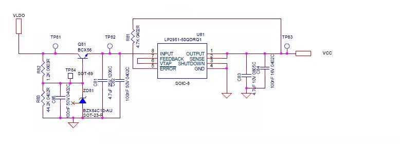
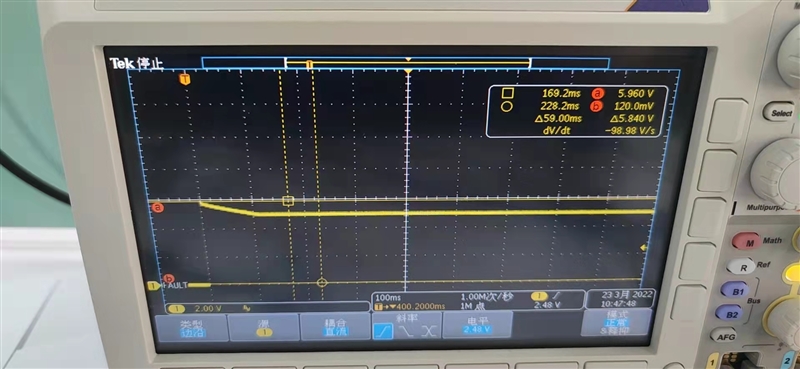
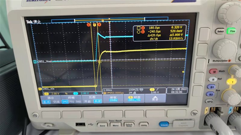
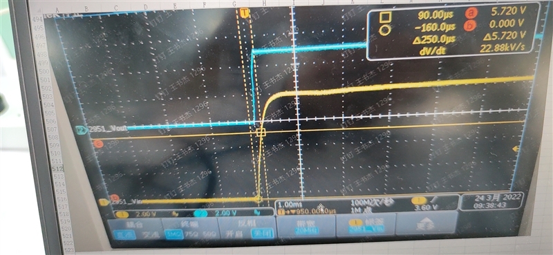
The start up output waveform and schematic are as below, the spike is up to 6V, the capacitors are all ceramic but we have tried adding 1Ohm resistors, and disconnected the load, the waveform are same, could you please give me some comments? Thanks. 

  • Hi Wayne, 

    What is the input Voltage at TP82?

    What is the Output load? Do you have a ILOAD Waveform?

    Have you attempted increasing your output capacitance? - Please reference section 8.2.2.1 in the datasheet.

    Figure 8 of this APP note shows typical behavior with large output capacitor values: https://www.ti.com/lit/an/slyt151/slyt151.pdf

    Also, for the Error pin:

    The output of the comparator is rated to sink up to 400 μA. A suitable range of values for the pullup resistor is from 100 kΩ to 1 MΩ - reference Figure 34 in the datasheet.

    This may be acting like a load. 

    Best,

    Juliette 

  • Hi Juliette,

    Thanks for your help.

    Below is the voltage waveform of TP82. 

    The LDO is a CAN transceiver, they disconnected the load test measured the waveform, same overshoot.

    Increased the output cap to 40uF, the overshoot decreased to 5.4V from 6V but the cap is too big to be acceptable. 

    Removed the error pin resistor,  it doesn't work.

    Below the first picture is 4.7uF output cap, blue curve is output and yellow is input.

    The second picture is 2.2uF output cap, so strange that the overshoot disappears, could you please explain why? Thanks. 

  • Hi Wayne, 

    How are you using the LDO as a CAN transiever? https://www.ti.com/lit/an/slla109a/slla109a.pdf

    This App note describes the LDO functionality in the TCAN4550-Q1 https://www.ti.com/lit/an/slla441/slla441.pdf?

    If you are using the Error Pin functionality, you need to connect a larger resistor, otherwise you can leave it floating. 

    the error amplifier has a slower transient response which can cause the output to overshoot significantly when the device is recovering from a dropout condition. Faster ramp rates result in more overshoot and may require a zener diode on the output to limit the VOUT overshoot.

    Looking at the Input of the device, it seems like the device may be entering dropout. To test this - please increase the speed of the start-up ramp rate. 

    You can do this by using your shutdown pin as an enable pin and having your VIN at a stable voltage beforehand. 

    If you have a Current probe, it may be beneficial to see that too.