This thread has been locked.

If you have a related question, please click the "Ask a related question" button in the top right corner. The newly created question will be automatically linked to this question.

LM5176-Q1: Spread Spectrum LM5176QPWPTQ1

Part Number: LM5176-Q1
Other Parts Discussed in Thread: LM5176

Hi team,

My customers are planning to use LM5176QPWPTQ1 IC in our design.

How to enable the Spread Spectrum feature of this IC?

Thank you very much for your help.

Best regards,

  • Hi Zhonghui,

    in the datasheet this feature can be found under "DITHER"

    Best regards,

     Stefan

  • Hi  Stefan,

    Thank you for your quick feedback.

    My customers have tried to use all the components as suggested in the reference e design, but few parts are different . For example MOSFETs, I/O Capacitors. Can you please review this design? Our requirement is 9V-36VIN, 12V VOUT, 11A with spread spectrum. I have attached here the schematics for review and referred schematics . Thanks

    Best regards,

  • Hi Zhonghui,

    will look into this but it can take some time, may come back mid of next week.

    Meanwhile you might use the design calculator to check the circuit:

    LM5176-Q1 data sheet, product information and support | TI.com

    Best regards,

     Stefan

  • Hi  Stefan,

    Thank you for your help.

    I have made some changes in the design. I have attached modified files for your review.

    TI Sch.zip

    I have one question about the MOSFET specifications. In the simulation, the higher end MOSFETs are 100A and Lower end are smaller. What is the lower current limit I can go with at these MOSFETs. This is just to reduce BOM cost and size of the parts. thanks.

    Best regards,

  • Hi Zhonghui,

    from the basic converter you should see ~20 A with adding some margin and headroom this will go to ~ 25A.

    The current limit set with the Rsense is 23.4A

    Note: the Current sense resistor is to high -> worst case it can already trigger in normal operating condition.

    So I would take the highest Current sense limit and add a 20% margin for the lower limit of the FETs.

    Best regards,

     Stefan

  • Hi  Stefan,

    Thanks for the response. Our load current requirement is 11A. So is this 23.4A set by Rsense too much for the required load current? Should I reduce this current limit to something like 15A? I did not calculate this by myself, I have taken these values out of simulation design. Please suggest.

    based on your suggestion, I have changed the Lower End MOSFETs to 53A, which is definitely higher than 20% of25A. I will be waiting for your review on the complete schemtaics. Thanks

    Best regards,

  • Hi Zhonghui,

    you need to decrease the current sense resistor, to increase the current limit.

    Which tool have you used for the estimation of the current sense Resistor (you mentioned a simulation tool).

    Have you used the Design Calculator: LM5176-Q1 data sheet, product information and support | TI.com

    This is general the tool i am using for checking out designs.

    Best regards,

     Stefan

  • Hi Zhonghui,

    added series 0 Ohm Resistor into the Gate line of the FET is also a good practice so that it is easy to add a resistor in case it is required.

    Is there a reason why Dboot1 and Dbout2 are different?

    Best regards,

     Stefan

  • Hi  Stefan,

    Thanks for the response.

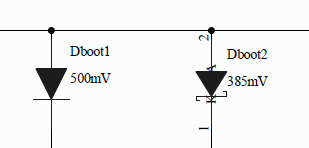
    I used TI's WEb Bench Designer, online tool. I put all the design requirements like VIN VOUt, IOT etc and I got the design. I have attached here the schematics I received from WEbbench tool. It is designed for 11A IOUT.Dboot1 and Dbout2 are not different , they are same part PMEG6010CEH.

    Best regards,

  • HI Zhonghui,

    for the Diode i got fooled by this in the schematic:

    While reviewing the information in this thread i have seen that there are two different schematics:

    - in 1. entry attached.

    - in zip file as pdf

    - in zip file as altium file

    Can you please clarify which one is the actual/correct one.

    I am just working with the Webench team is I think there is an issue with the model not properly considering all modes.

    Please use the Design Caluculator from the product page: LM5176-Q1 data sheet, product information and support | TI.com

    in the mean time.

    Best regards,

     Stefan

  • Hi  Stefan,

    I have attached here a PDF with latest schematics for your review. The file name is "DTI_12V 11A LM5176_300322". 

    meanwhile I have tries the online calculator and I have attached it here. Please correct me if my understanding is wrong.
    1. I can still use 1.5uH inductor. (Recommended is 2uH)
    2. The current inductor I chose is 1.5uH,27A normal current, 47A Saturation current is ok.
    3. The RSENSE need to be changed to 5mOhms. I have considered 15 A as maximum load current and 11A as normal load current
    4. Current Output capacitors are total 160uF. I can still reduced theses to 68uF as suggested in the calculator.
    5. Input capacitors are ok
    6. Soft start, Dither are ok
    7. UVLO, I need to change R43 to 36.5Kohm
    8. Compensation Network components are ok
    9. Selected MOSFETs are ok

    Please let me know your comments and any changes need to be done in the design.

    Thanks for the help.

    Best regards,

  • Hi Zhonghui,

    please see my comments below:

    - Ground connection should be moved from (R198) to the shunt (R210). In the schematic this is editorial on the board this is essential.

    - for slope compensation i would start with 100pF and the optimize once the board is available.

    - UVLO level is at 7.6V compared to 9V Vin ? - check if this is the required level.

    Best regards,

     Stefan

  • Hi  Stefan,

    Thank for your comments. I will fix these issues in the design. Apart from these is everything else ok? Thanks

    Best regards,

  • HI Zhonghui,

    no, I have not seen further items.

    Best regards,

     Stefan

  • Hi  Stefan,

    Thank for your help.

    Best regards,